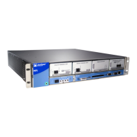
Table 54: DB-9 Connector Pinout
DescriptionDirectionSignalPin
Carrier Detect<–DCD1
Receive Data<–RxD2
Transmit Data–>TxD3
Data Terminal Ready–>DTR4
Signal Ground—Ground5
Data Set Ready<–DSR6
Request To Send–>RTS7
Clear To Send<–CTS8
Ring Indicator<–RING9
Related
Documentation
• M7i Routing Engine Description on page 17
• Maintaining the M7i Routing Engine on page 192
• Replacing the M7i Routing Engine on page 141
• Replacing the Routing Engine Interface Port Cables on page 144
• RJ-45 Connector Pinouts for the M7i Routing Engine MGMT Port on page 98
99Copyright © 2019, Juniper Networks, Inc.
Chapter 13: Management Cable and Transceiver Specifications and Pinouts

 Loading...