Connecting the M7i Router to a Network for Out-of-Band Management
To connect the Routing Engine to a network for out-of-band management, insert an
Ethernet cable with RJ-45/RJ-45 connectors into the MGMT port on the Routing Engine.
One such cable is provided with the router (see “Routing Engine Interface Cable and Wire
Specifications for the M7i Router” on page 97). Follow this procedure:
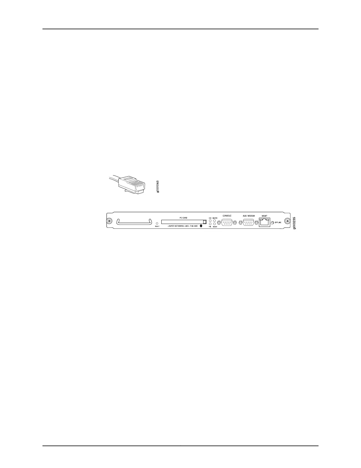
1. Plug one end of the Ethernet cable (Figure 31 on page 116 shows the connector) into
the MGMT port on the Routing Engine Figure 32 on page 116 shows the layout of the
ports on the Routing Engine.
2. Plug the other end of the cable into the network device.
Figure 31: Routing Engine Ethernet Cable Connector
Figure 32: Routing Engine Interface Ports
See Also M7i Power System Description on page 59•
• M7i Router Power Requirements on page 79
• M7i Router Site Preparation Checklist on page 73
Connecting the M7i Router to a Management Console or Auxiliary Device
To use a system console to configure and manage the Routing Engine, connect it to the
CONSOLE port on the Routing Engine. To use a laptop, modem, or other auxiliary device,
connect it to the AUX/MODEM port on the Routing Engine. Both ports accept an RS-232
(EIA-232) serial cable with DB-9/DB-9 connectors. One such cable is provided with the
router. If you want to connect a device to both ports, you must supply another cable. See
“Routing Engine Interface Cable and Wire Specifications for the M7i Router” on page 97.
To connect a management console or auxiliary device:
1. Turn off the power to the console or auxiliary device.
2. Plug the female end (shown in Figure 33 on page 117) of the provided console cable
into the CONSOLE or AUX/MODEM port. “Routing Engine Interface Ports” on page 116
shows the layout of the ports on the Routing Engine.
Copyright © 2019, Juniper Networks, Inc.116
M7i Multiservice Edge Router Hardware Guide