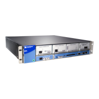
LEDs on Hardware Components
LEDs on the faceplates of many hardware components report component status:
•
AC power supply—A green LED labeled OUTPUT OK. For more information, see “M7i
AC Power Supply” on page 60.
•
Routing Engine—Four LEDs on the Routing Engine faceplate indicate the status of the
Routing Engine. Two upper LEDs—a green one labeled HDD, and a blue one labeled
MASTER—and two lower LEDs—a red one labeled FAIL, and a green one labeled ONLINE.
For more information, see “M7i Routing Engine Description” on page 20.
•
PIC—Most PICs have an LED labeled STATUS on the PIC faceplate. Some PICs have
additional LEDs, often one per port. The meaning of the LED states differs for various
PICs. For more information, see the M7i Multiservice Edge Router Interface Module
Reference.
•
CFEB or CFEB-E—A green LED labeled OK, a red one labeled FAIL, and a blue one
labeled MASTER. For more information, see “M7i Compact Forwarding Engine Board
(CFEB) and Enhanced Compact Forwarding Engine Board (CFEB-E) Description” on
page 69.
Hardware and Interface Alarm Messages
When the Routing Engine detects an alarm condition, it lights the red or yellow alarm
LED on the FIC. To view a more detailed description of the alarm cause, issue the
show chassis alarms CLI command.
There are two classes of alarm messages:
•
Chassis alarms—Indicate a problem with a chassis component such as the cooling
system or power supplies, as described in Table 59 on page 200.
•
Interface alarms—Indicate a problem with a specific network interface, as described
in Table 60 on page 203.
Table 59: Chassis Alarm Messages
Alarm
SeverityRemedyAlarm Condition
Chassis
Component
YellowContact technical
support.
See“Contacting
Customer Support” on
page 211 for more
information.
The router has an CompactFlash card
but boots from alternate boot device.
If you configure your router to boot
from the hard disk, ignore this alarm
condition.
Alternative
Media
Copyright © 2019, Juniper Networks, Inc.200
M7i Multiservice Edge Router Hardware Guide

 Loading...