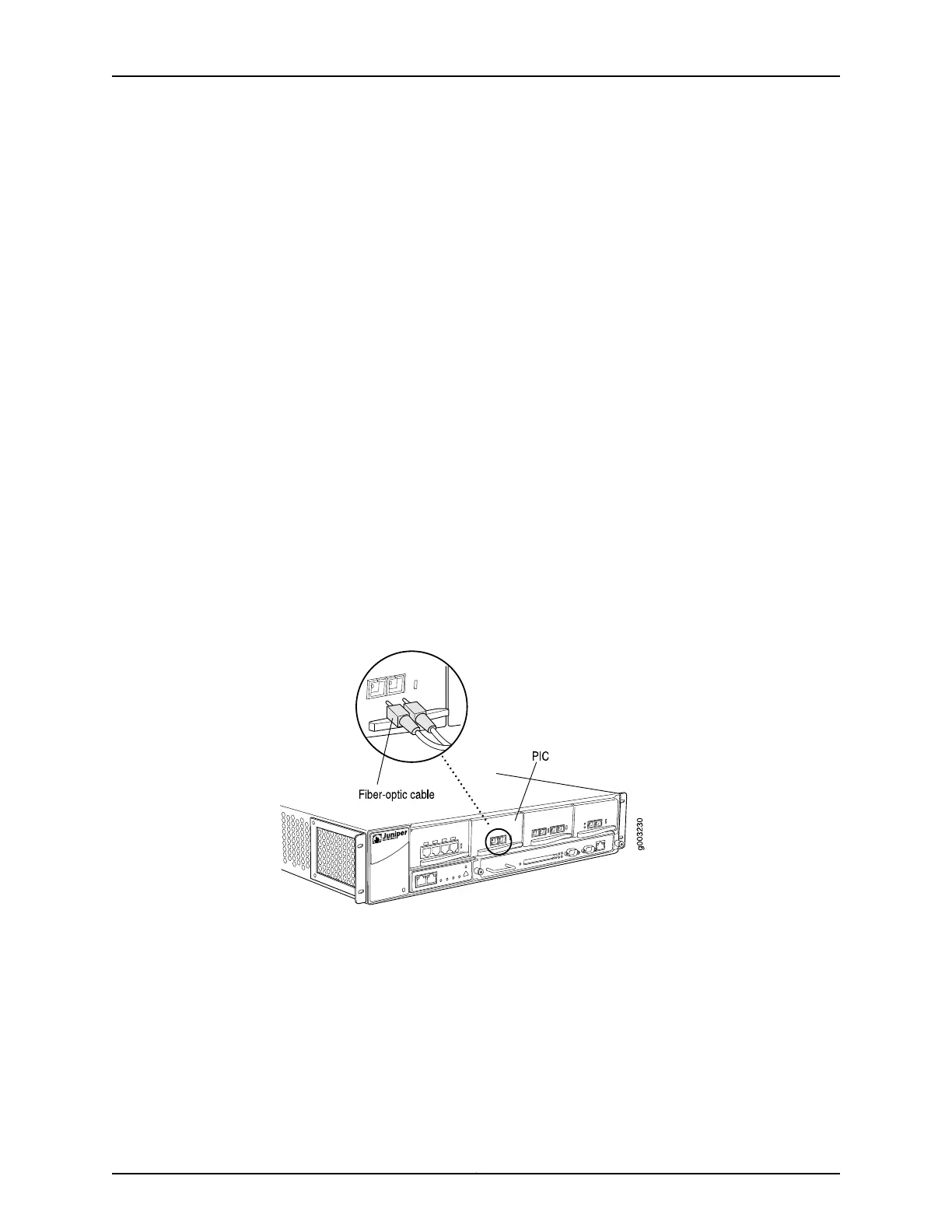
To install a PIC cable (see Figure 59 on page 165):
1. Have ready a length of the type of cable used by the interface, as specified in “FIC
Specifications for the M7i Router” on page 45.
2. If the interface cable connector port is covered by a rubber safety plug, remove the
plug.
3. Insert the cable connector into the cable connector port on the interface faceplate.
4. Arrange the cable to prevent it from dislodging or developing stress points. Secure
the cable so that it is not supporting its own weight as it hangs to the floor. Place
excess cable out of the way in a neatly coiled loop. Placing fasteners on the loop helps
to maintain its shape.
6. Verify that the FIC or PIC is functioning correctly by noting whether the normal function
indicator LED is lit. The normal function indicator LED is usually green; for more
information, see the M7i Multiservice Edge Router Interface Module Reference.
You can also verify correct PIC functioning by issuing the show chassis fpc pic-status
command, described in “Maintaining the M7i FIC and FIC Cables and PICs and PIC
Cables” on page 192.
Figure 59: Connecting Fiber-Optic Cable to a PIC
See Also M7i Flexible PIC Concentrators (FPCs) Description on page 43•
• M7i PICs Description on page 46
• Removing an M7i FIC or PIC Cable on page 163
• Troubleshooting the M7i FIC or PICs on page 205
Related
Documentation
M7i Flexible PIC Concentrators (FPCs) Description on page 43•
165Copyright © 2019, Juniper Networks, Inc.
Chapter 24: Replacing Line Card Components