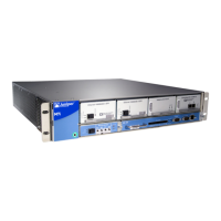
M7i and M10i Packet Forwarding Engine Architecture
The Packet Forwarding Engine performs Layer 2 and Layer 3 packet switching. The Packet
Forwarding Engine is implemented in application-specific integrated circuits (ASICs). It
uses a centralized route lookup engine and shared memory.
•
Packet Forwarding Engine Components on page 5
•
Data Flow Through the Packet Forwarding Engine on page 5
Packet Forwarding Engine Components
The Packet Forwarding Engine architecture includes the following components:
•
Midplane—Transports packets, notifications, and other signals between the FPCs and
the Packet Forwarding Engine (as well as other system components).
•
Physical Interface Card (PIC)—Physically connects the router to fiber-optic or digital
network media. A controller ASIC in each PIC performs control functions specific to
the PIC media type.
•
Compact Forwarding Engine Board (CFEB) or Enhanced Compact Forwarding Engine
Board (CFEB-E)—Hosts an integrated ASIC, which makes forwarding decisions,
distributes data cells to the shared memory, and directs data packets when they are
ready for transmission.
Data Flow Through the Packet Forwarding Engine
Use of ASICs promotes efficient movement of data packets through the system. Packets
flow through the Packet Forwarding Engine in the following sequence (see
Figure 2 on page 6):
1. Packets arrive at an incoming networking interface.
2. The networking interface passes the packets to the CFEB or CFEB-E, where the
integrated ASIC processes the packet headers, divides the packets into 64-byte data
cells, and distributes the data cells throughout the memory buffer.
3. The integrated ASIC on the CFEB or CFEB-E performs a route lookup for each packet
and decides how to forward it.
a. If services are configured for the packet, the integrated ASIC reassembles the
packet and passes them to the services interface.
b. The services interface passes the packet to the CFEB or CFEB-E, where the
integrated ASIC processes the packet, divides the packet into 64-byte cells, and
distributes the data cells throughout the memory buffer.
5Copyright © 2019, Juniper Networks, Inc.
Chapter 1: System Overview and Architecture

 Loading...