3. Pull the ejector lever away from the PIC faceplate and hold it while you insert the PIC.
4. Align the rear of the PIC with the guides located at the bottom corners of the PIC slot.
5. Slide the PIC into the card cage until about 0.5 in. (1 cm) of the PIC remains outside
the slot and you feel some resistance. Release the ejector lever.
CAUTION: Be careful to insert the PIC straight into the chassis to avoid
damaging the components on the bottom of the PIC.
6. Continue pushing the PIC until it contacts the midplane and you hear a click. The
ejector lever engages and closes automatically.
7. If the PIC uses fiber-optic cable, remove the rubber safety cap from each transceiver.
8. Insert the appropriate cable into the cable connector ports on the PIC.
9. Arrange the cable to prevent it from dislodging or developing stress points. Secure
the cable so that it is not supporting its own weight as it hangs to the floor. Place
excess cable out of the way in a neatly coiled loop. Placing fasteners on the loop helps
to maintain its shape.
10. Press and hold the PIC offline button on the FIC until the normal function indicator
LED lights, which usually takes about 5 seconds. The normal function indicator LED
is usually green; for more information, see the M7i Multiservice Edge Router Interface
Module Reference.
You can verify correct PIC functioning by issuing the show chassis fpc pic-status command,
described in “Maintaining the M7i FIC and FIC Cables and PICs and PIC Cables” on page 192.
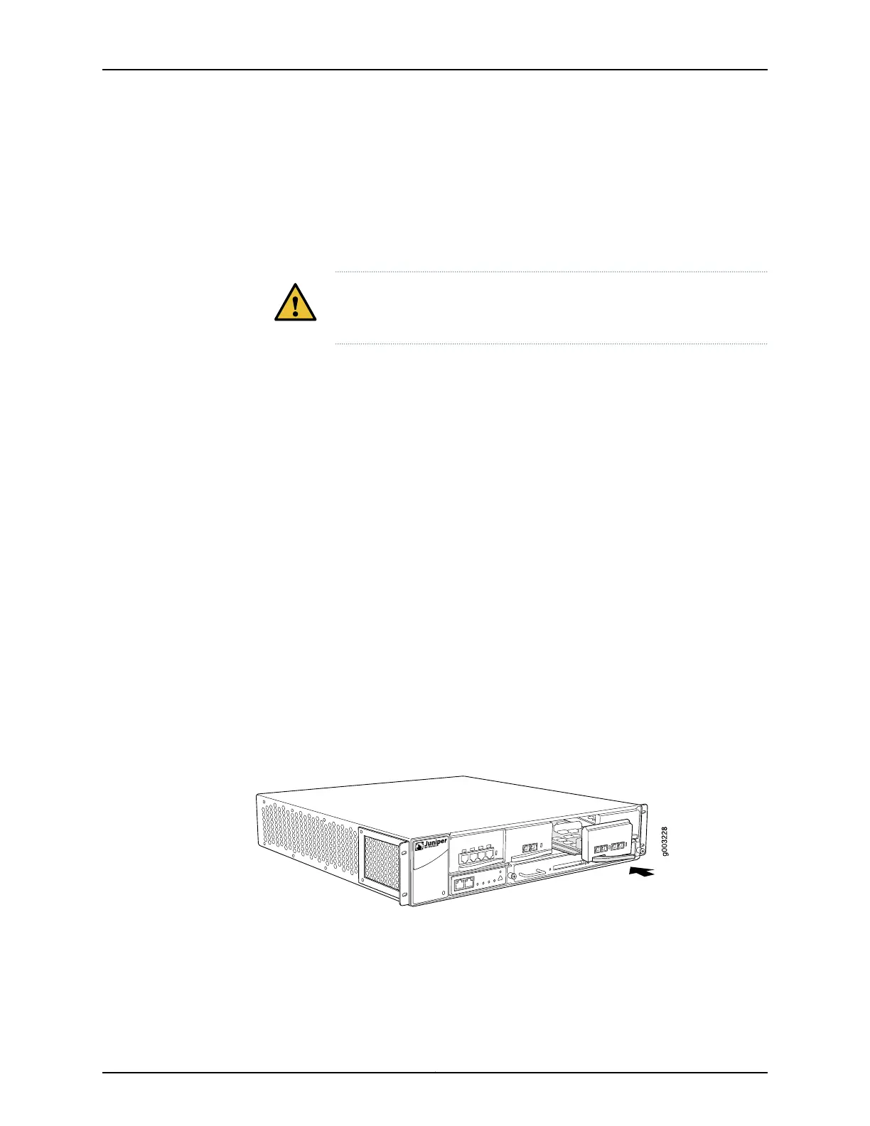
Figure 58: Installing a PIC
See Also M7i PICs Description on page 46•
• M7i Chassis Description on page 11
• M7i Midplane Description on page 12
Copyright © 2019, Juniper Networks, Inc.162
M7i Multiservice Edge Router Hardware Guide