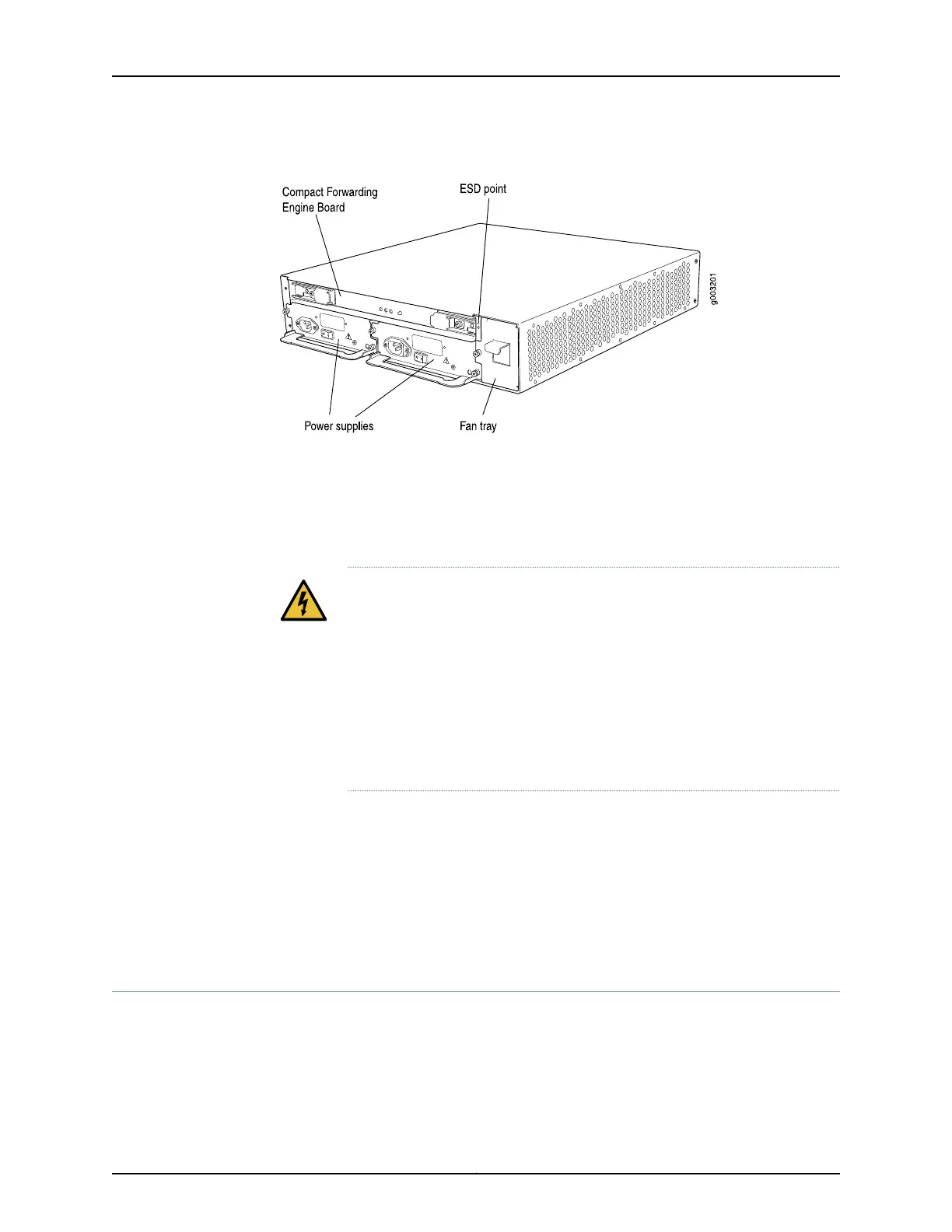
Figure 6: Rear of Chassis
The chassis includes the following electrical safety components:
•
One electrostatic discharge (ESD) points (banana plug receptacles), at the front of
the chassis, as shown in Figure 5 on page 11.
•
Two internally threaded inserts providing grounding points for the router.
WARNING: Beforeremoving or installing componentsofafunctioningrouter,
attach an ESD strap to an ESD point and place the other end of the strap
around your bare wrist. Failure to use an ESD strap could result in damage
to the router.
The router must be connected to earth ground during normal operation.
For further safety information, see “General Safety Guidelines for Juniper
Networks Devices” on page 225 and “General Safety Warnings for Juniper
Networks Devices” on page 226.
For chassis serial number information , see “Displaying M7i Router Components and Serial
Numbers” on page 213.
Related
Documentation
M7i Router Physical Specifications on page 74•
• Overview of M7i Router Installation on page 103
• M7i Router Description on page 3
M7i Midplane Description
The midplane is a panel located in the center of the chassis, running from side to side
and forming the rear of the PIC card cage (see Figure 7 on page 13). All router components
plug directly into the midplane. The midplane contains an EEPROM that stores the serial
number and revision level of the midplane.
Copyright © 2019, Juniper Networks, Inc.12
M7i Multiservice Edge Router Hardware Guide