RJ-45 Connector Pinouts for the M7i Routing Engine MGMT Port
The port on the Routing Engine labeled MGMT is an autosensing 10/100-Mbps Ethernet
RJ-45 receptacle that accepts an Ethernet cable for connecting the Routing Engine to a
management LAN (or another device that supports out-of-band management).
Table 53 on page 98 describes the RJ-45 connector pinout.
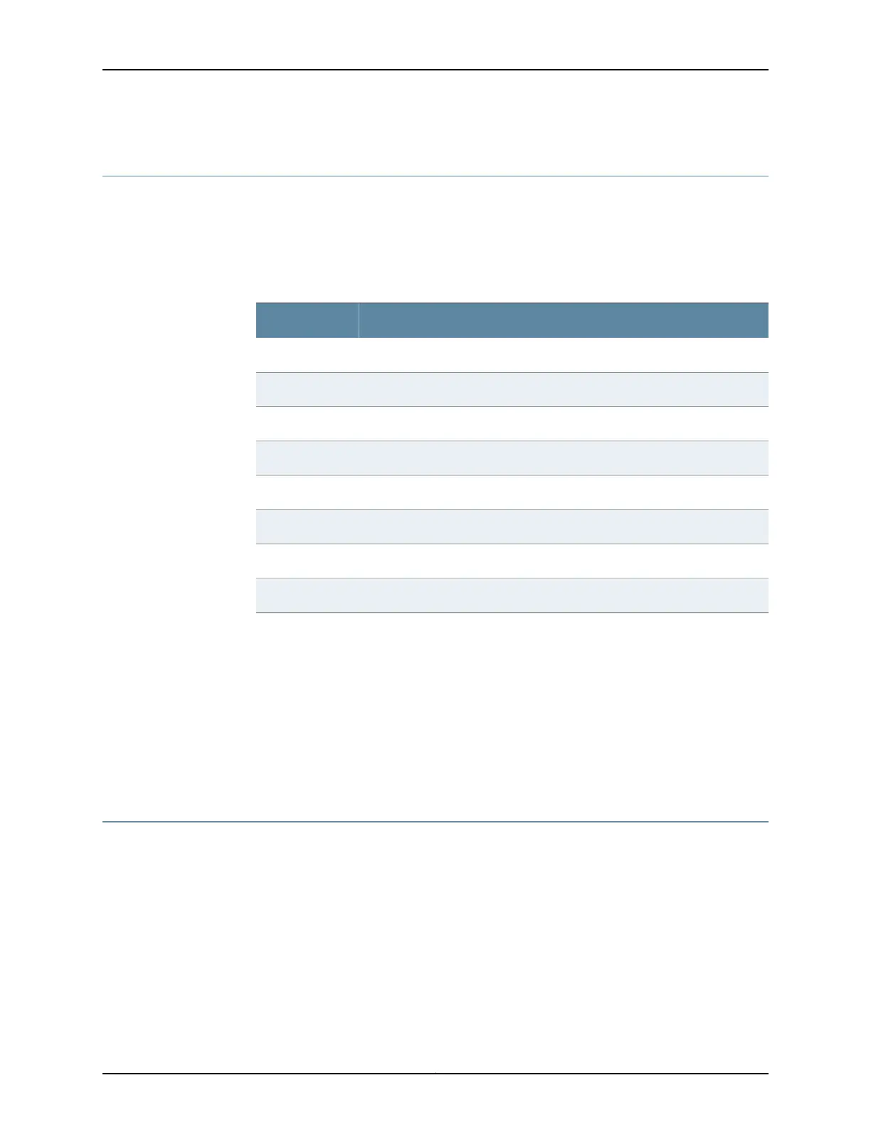
Table 53: RJ-45 Connector Pinout
SignalPin
TX+1
TX-2
RX+3
Termination network4
Termination network5
RX-6
Termination network7
Termination network8
Related
Documentation
M7i Routing Engine Description on page 17•
• Maintaining the M7i Routing Engine on page 192
• Replacing the M7i Routing Engine on page 141
• Replacing the Routing Engine Interface Port Cables on page 144
• DB-9 Connector Pinouts for the M7i Routing Engine AUX/MODEM and CONSOLE Ports
on page 98
DB-9 Connector Pinouts for the M7i Routing Engine AUX/MODEM and CONSOLE Ports
The ports on the CIP labeled AUX/MODEM and CONSOLE are DB-9 receptacles that
accept RS-232 (EIA-232) cable. The AUX/MODEM port connects the Routing Engine to
a laptop, modem, or other auxiliary unit, and the CONSOLE port connects it to a
management console. The ports are configured as data terminal equipment (DTE).
Table 54 on page 99 describes the DB-9 connector pinouts.
Copyright © 2019, Juniper Networks, Inc.98
M7i Multiservice Edge Router Hardware Guide

 Loading...


