4-4 Keysight B1505A Configuration and Connection Guide
N1272A and N1273A Connection Guide
Input Connection
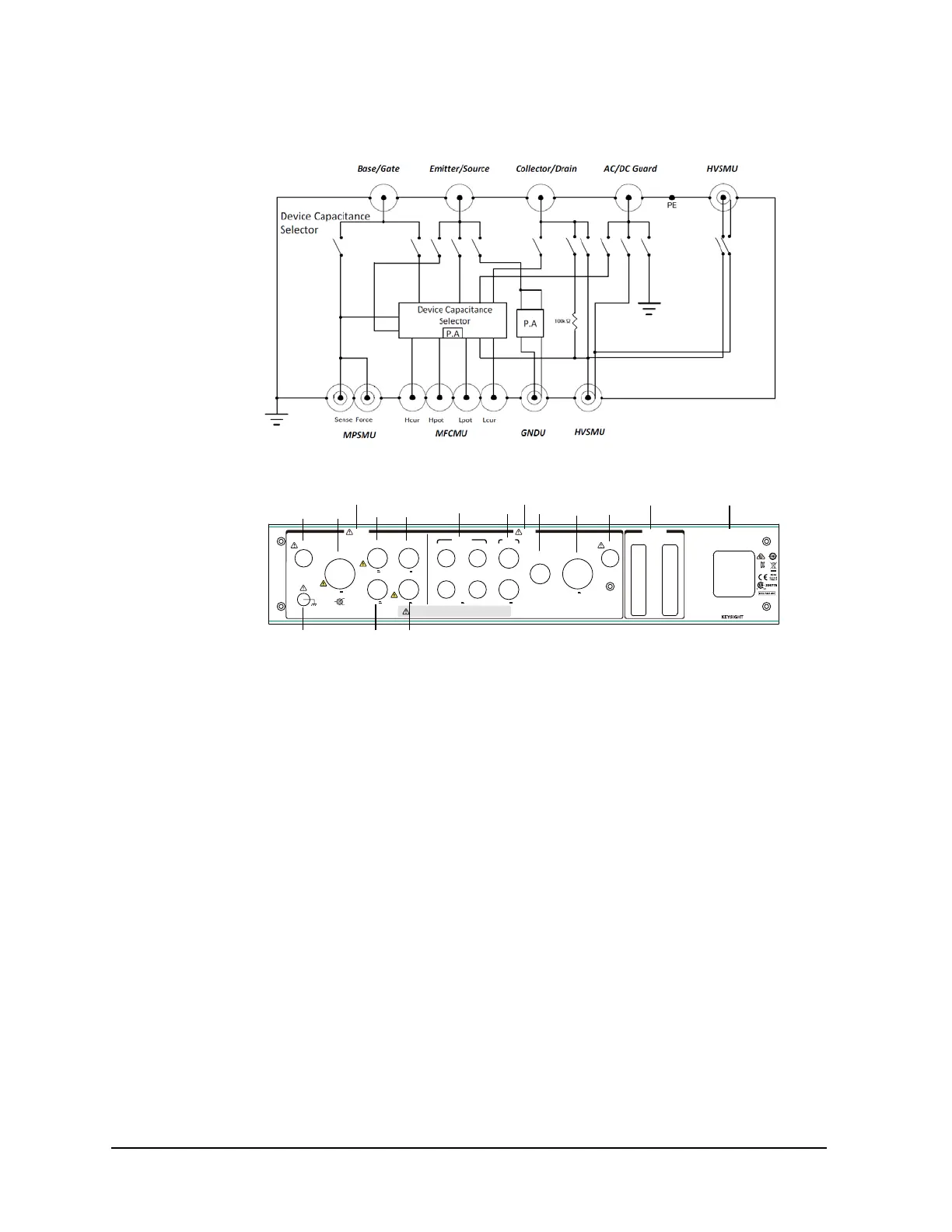
Figure 4-2 Selector Simplified Internal Connections
Figure 4-3 N1272A Rear View
1. Digital I/O connectors
2. Input
a. MFCMU input connectors Hcur, Hpot, Lpot, and Lcur
b. SMU input connectors
c. GNDU input connector
d. HVSMU input connector
e. Interlock input connector
3. Output
a. Collector/Drain output connector
b. Base/Gate output connector
c. Emitter/Source output connector
d. AC/DC Guard output connector
e. HVSMU output connector
f. Interlock output connector
g. Frame ground terminal
4. LINE input receptacle and power switch
Force
Guard
Circuit
Common
HVSMU
To avoid electrical shock and instrument damage,
do not connect/disconnect the cables during operation.
Output Input
±3 k V Max
Lcur
Hcur
Lpot
Hpot
Force
Sense
±3 k V Max±3 k Max
±3 k
V
Max
±100 V Max
±100 V Max
±3 k
V
Max ±25 V Max ±100 V Max
~
LINE
100
-
240 V
~
50/60 Hz
70 VA Max
Input Output
Digital I/O
HVSMU
Base/Gate
MFCMU SMU
GNDU
Collector/Drain
AC/DC GuardEmitter/Source
Interlock
Interlock
MSIP-REM-ATI-
1H-B1507A
T2 T1
T3 T4
N1272
-
61001

 Loading...


