N9030B PXA Signal Analyzer Service Guide 461
Assembly Replacement Procedures
RF Area (Options 503, 508, 513, 526)
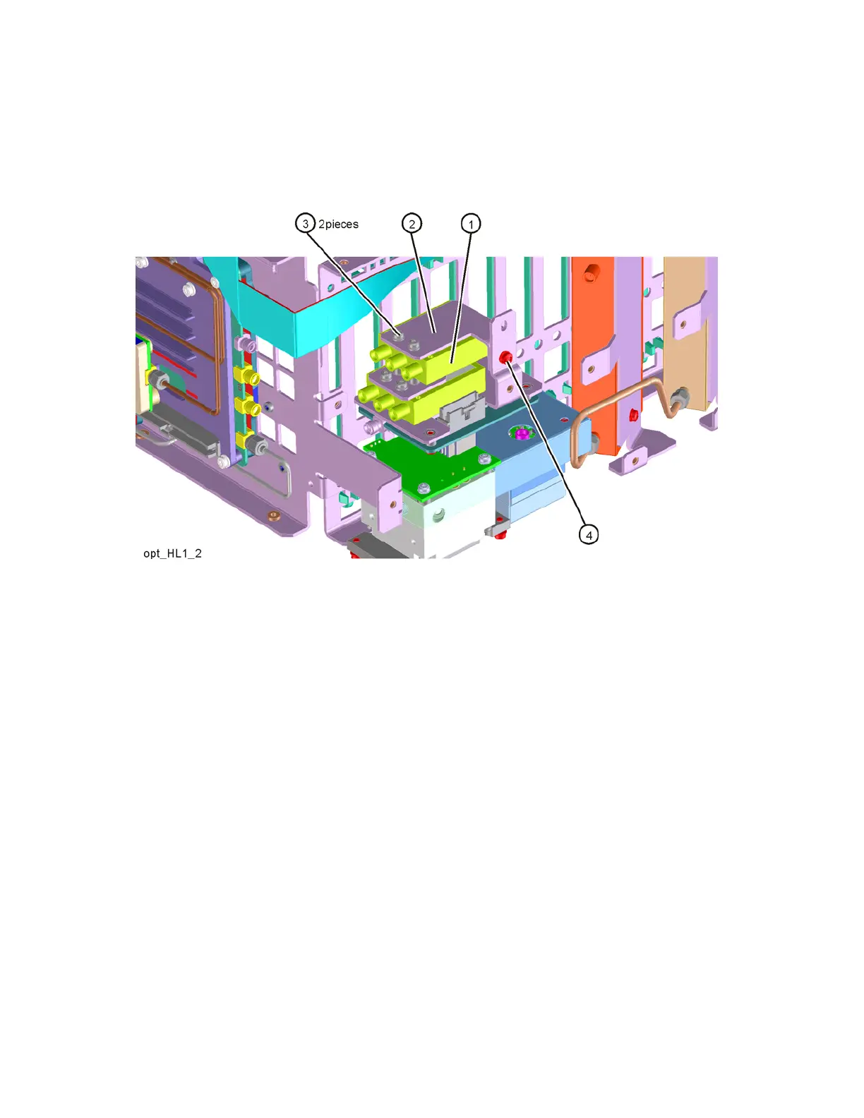
2. Refer to Figure 16-29. Place the second switch/bracket assembly (1)/(2)
on the bracket previously installed. Assure label on switch is facing up. To
attach use the two screws (3) (0515-1992).
Figure 16-29 Switch 2 Placement
3. Secure the bracket to the Low Band Switch bracket with the single screw
(4) (0515-0372). Do not torque.
4. Align switches so they are parallel with side of instrument then torque the
four screws (3) securing the switches to the brackets to 6 in lbs. Torque
the screw (4 ) that secures the switch brackets together to 9 inch-lbs.