462 N9030B PXA Signal Analyzer Service Guide
Assembly Replacement Procedures
RF Area (Options 503, 508, 513, 526)
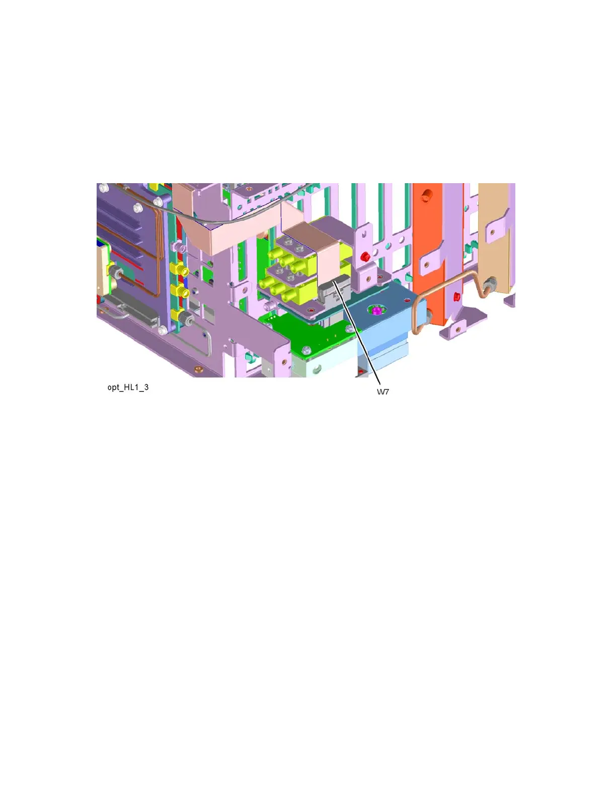
5. Refer to Figure 16-30. Route W7 over bracket and switch as shown and
insert W7 connector into Low Band Switch header. Ensure the locking tabs
are engaged on both sides of the connector.
Figure 16-30 W7 Routing