EasyManuals Logo

Keysight Technologies N9030B User Manual

Keysight Technologies N9030B
617 pages
To Next Page IconTo Next Page
To Previous Page IconTo Previous Page
Page #470 background imageLoading...
Page #470 background image
470 N9030B PXA Signal Analyzer Service Guide
Assembly Replacement Procedures
RF Area (Options 503, 508, 513, 526)
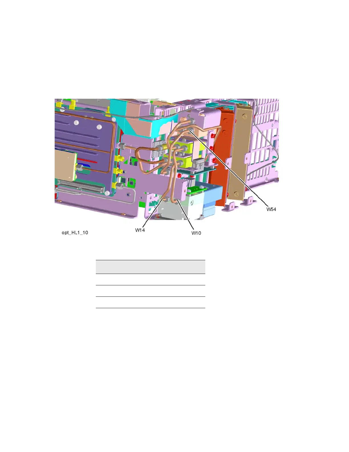
14.Refer to Figure 16-39. Install rigid cable W54 (N9020-20145) (1) from top
switch port 3 to Low Band Switch Assembly as shown. Torque to
10 inch-lbs.
Figure 16-39 W10, W14, W54 Installation
15.Install rigid cable W14 (E4410-20165) (2) from bottom switch port 2 to
YTF Assembly as shown. Torque to 10 inch-lbs.
16.Install rigid cable W10 (E4410-20163) (3) from middle switch port 2 to
YTF Assembly as shown. Torque to 10 inch-lbs.
Table 16-9
Item Keysight Part Number
W10 E4410-20163
W14 E4410-20165
W54 N9020-20145

Table of Contents

Other manuals for Keysight Technologies N9030B

Questions and Answers:

Question and Answer IconNeed help?

Do you have a question about the Keysight Technologies N9030B and is the answer not in the manual?

Keysight Technologies N9030B Specifications

General IconGeneral
BrandKeysight Technologies
ModelN9030B
CategoryMeasuring Instruments
LanguageEnglish

Related product manuals