N9030B PXA Signal Analyzer Service Guide 469
Assembly Replacement Procedures
RF Area (Options 503, 508, 513, 526)
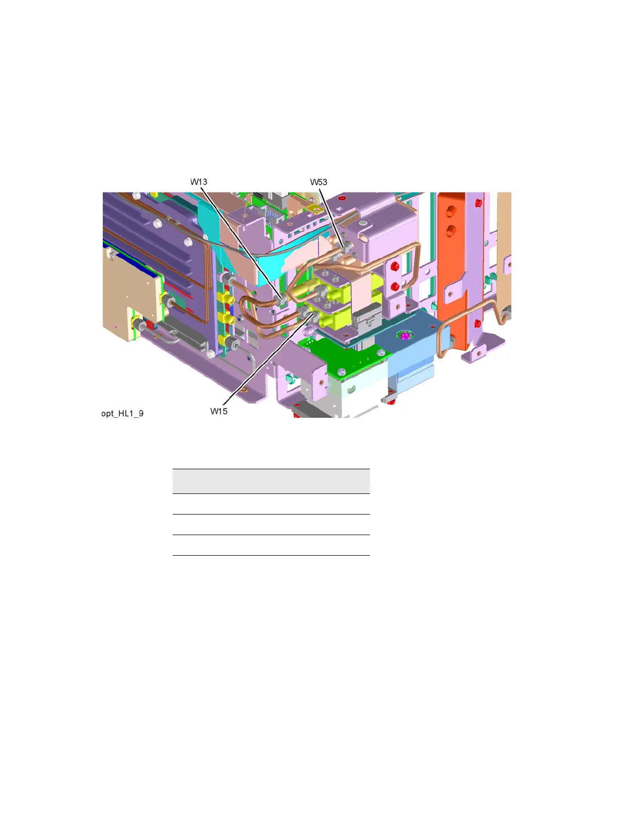
11.Refer to Figure 16-38. Install rigid cable W13 (N9020-20210) (1) between
attenuator (connected to center switch port 1 and bottom switch port 1.
Torque to 10 inch-lbs.
Figure 16-38 W13, W15, W53 Installation
12.Install rigid cable W53 (N9020-20144) (2) from top switch port 2 to
center switch center port. Torque to 10 inch-lbs.
13.Install rigid cable W15 (E4410-20164) (3) from bottom switch center port
to Front End Assembly J9. Torque to 10 inch-lbs.
Table 16-8
Item Keysight Part Number
W13 N9020-20210
W15 E4410-20164
W53 N9020-20144