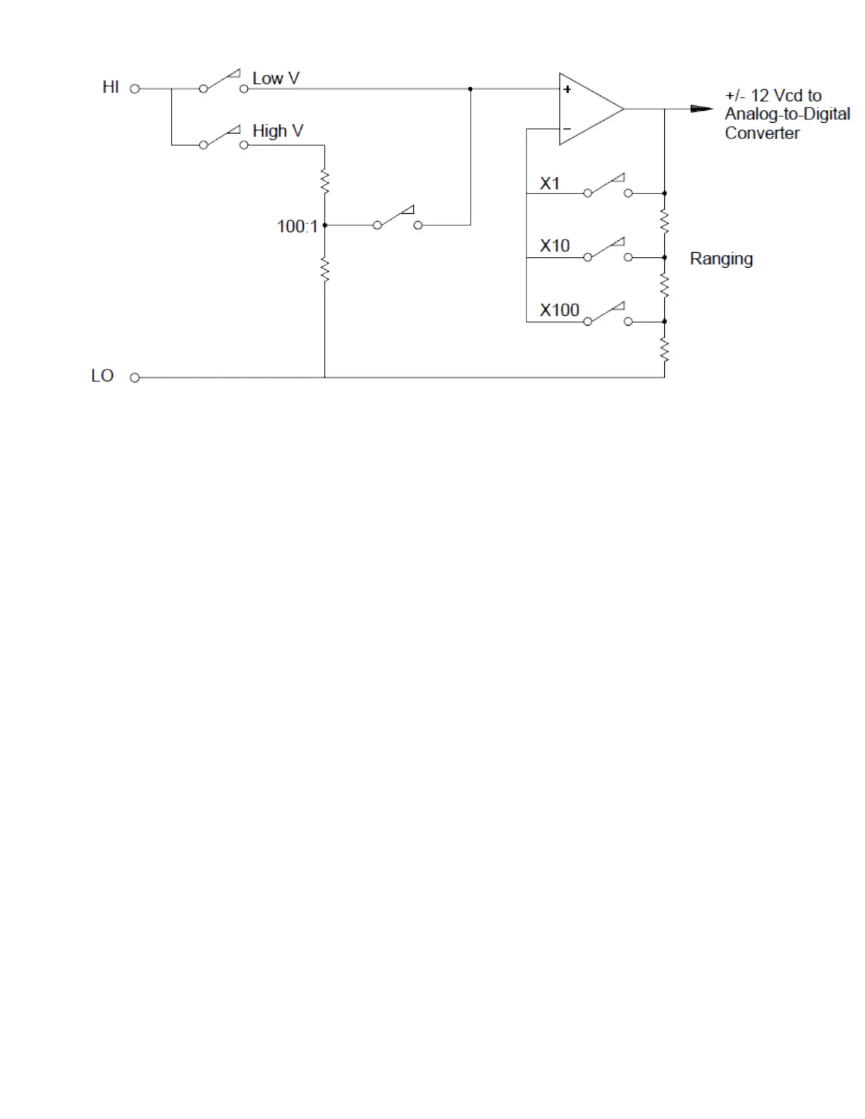
For input voltages less than 12 VDC, the Low V switch is closed and applies the input signal directly to the
input amplifier. For higher voltages, the High V switch is closed and the signal is attenuated 100:1 before
being applied to the input amplifier. The input amplifier gain is set to one of three values (x1, x10, or x100)
to yield a signal in the range of ±12 VDC for the analog-to-digital converter.
For the lower voltage ranges, the internal DMM’s input resistance is essentially that of the input amplifier.
The input amplifier uses a lowbias current (less than 50 pA) FET input stage yielding an input resistance
greater than 10 GΩ. On the 100V and 300V input ranges, the input resistance is determined by the total
resistance of the 100:1 divider. You can also set the input resistance to 10 MΩ by continuously closing the
High V switch.
4Measurement Tutorials
194 Keysight DAQ970A User's Guide