8.5.1 Connecting rod dimensions check
Important
Before assembling the connecting rod and pistons ( Par.
9.3.7 e 9.3.8 ), check that the difference in weight
between the complete connecting rod and piston units do
not exceed 8 gr to prevent weight imbalances during
rotation of the crankshaft and consequent damage.
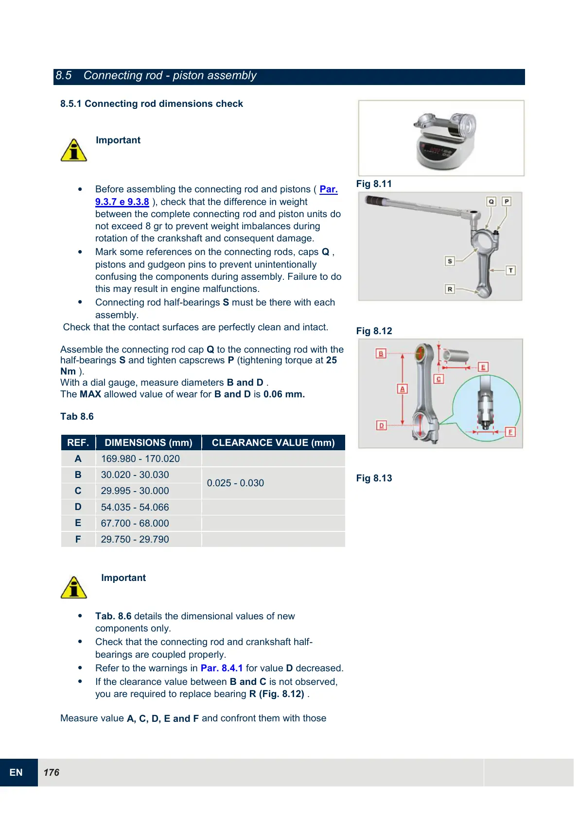
Mark some references on the connecting rods, caps Q ,
pistons and gudgeon pins to prevent unintentionally
confusing the components during assembly. Failure to do
this may result in engine malfunctions.
Connecting rod half-bearings S must be there with each
assembly.
Check that the contact surfaces are perfectly clean and intact.
Assemble the connecting rod cap Q to the connecting rod with the
half-bearings S and tighten capscrews P (tightening torque at 25
Nm ).
With a dial gauge, measure diameters B and D .
The MAX allowed value of wear for B and D is 0.06 mm.
Tab 8.6
Important
Tab. 8.6 details the dimensional values of new
components only.
Check that the connecting rod and crankshaft half-
bearings are coupled properly.
Refer to the warnings in Par. 8.4.1 for value D decreased.
If the clearance value between B and C is not observed,
you are required to replace bearing R (Fig. 8.12) .
Measure value
A, C, D, E and F
and confront them with those

 Loading...


