2.13 Electric system
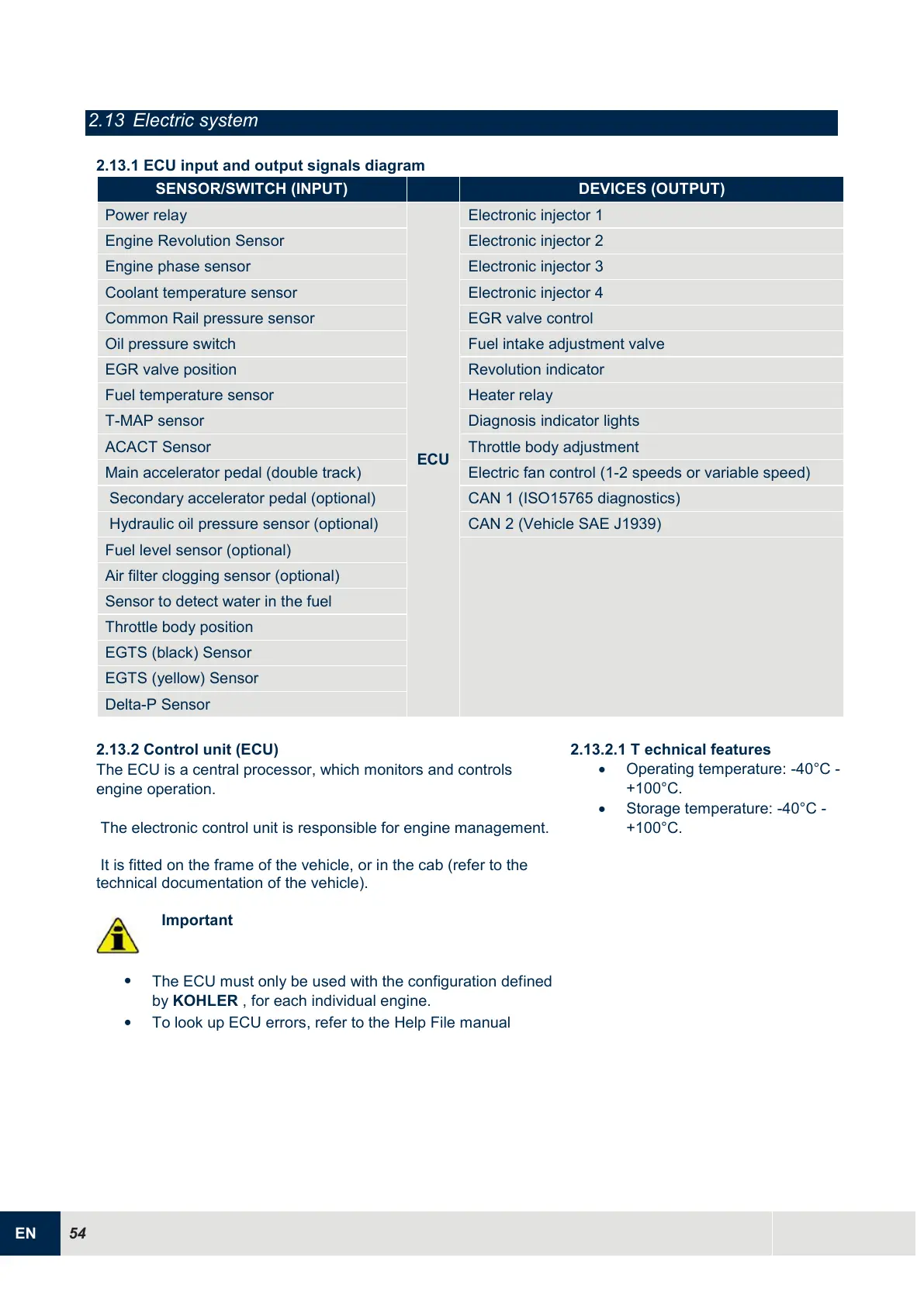
2.13.1 ECU input and output signals diagram
Coolant temperature sensor
Common Rail pressure sensor
Fuel intake adjustment valve
Diagnosis indicator lights
Main accelerator pedal (double track)
Electric fan control (1-2 speeds or variable speed)
Secondary accelerator pedal (optional)
CAN 1 (ISO15765 diagnostics)
Hydraulic oil pressure sensor (optional)
CAN 2 (Vehicle SAE J1939)
Fuel level sensor (optional)
Air filter clogging sensor (optional)
Sensor to detect water in the fuel
2.13.2
Control unit (ECU)
The ECU is a central processor, which monitors and controls
engine operation.
The electronic control unit is responsible for engine management.
It is fitted on the frame of the vehicle, or in the cab (refer to the
technical documentation of the vehicle).
Important
The ECU must only be used with the configuration defined
by KOHLER , for each individual engine.
To look up ECU errors, refer to the Help File manual
2.13.2.1 T echnical features
Operating temperature: -40°C -
+100°C.
Storage temperature: -40°C -
+100°C.

 Loading...


