8.4 Crankshaft
8.4.1 Dimensional check and overhauling
Wash the crankshaft thoroughly using suitable detergent.
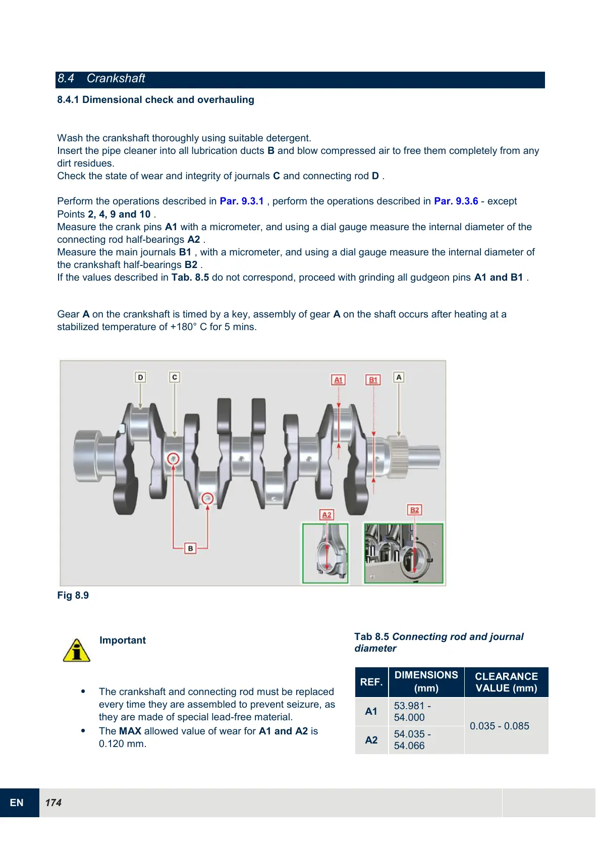
Insert the pipe cleaner into all lubrication ducts B and blow compressed air to free them completely from any
dirt residues.
Check the state of wear and integrity of journals C and connecting rod D .
Perform the operations described in Par. 9.3.1 , perform the operations described in Par. 9.3.6 - except
Points 2, 4, 9 and 10 .
Measure the crank pins A1 with a micrometer, and using a dial gauge measure the internal diameter of the
connecting rod half-bearings A2 .
Measure the main journals B1 , with a micrometer, and using a dial gauge measure the internal diameter of
the crankshaft half-bearings B2 .
If the values described in Tab. 8.5 do not correspond, proceed with grinding all gudgeon pins A1 and B1 .
Gear A on the crankshaft is timed by a key, assembly of gear A on the shaft occurs after heating at a
stabilized temperature of +180° C for 5 mins.
Fig 8.9
Important
The crankshaft and connecting rod must be replaced
every time they are assembled to prevent seizure, as
they are made of special lead-free material.
The MAX allowed value of wear for A1 and A2 is
0.120 mm.
Tab 8.5 Connecting rod and journal
diameter

 Loading...


