8.7.1 Dimensional and visual check
Perform the operations described in
Par.7.8.1 and Par.7.8.4.
Measure clearance value B between the rotor teeth, the
value of allowable wear is MAX 0.28 mm.
Clean all the components thoroughly, check that the work
surfaces C of the rotors and pump body are not worn.
Important
Should the results from checks carried out not be in
accordance with the conditions described, replace the
timing system carter together with the oil pump.
On assembly, references A must be visible.
8.7.2
R otors clearance check
Important
Replace carter
R
complete with its oil pump, if there are signs
of wear in area
P
of surface
Q (Fig. 8.32 - 8.32a)
.
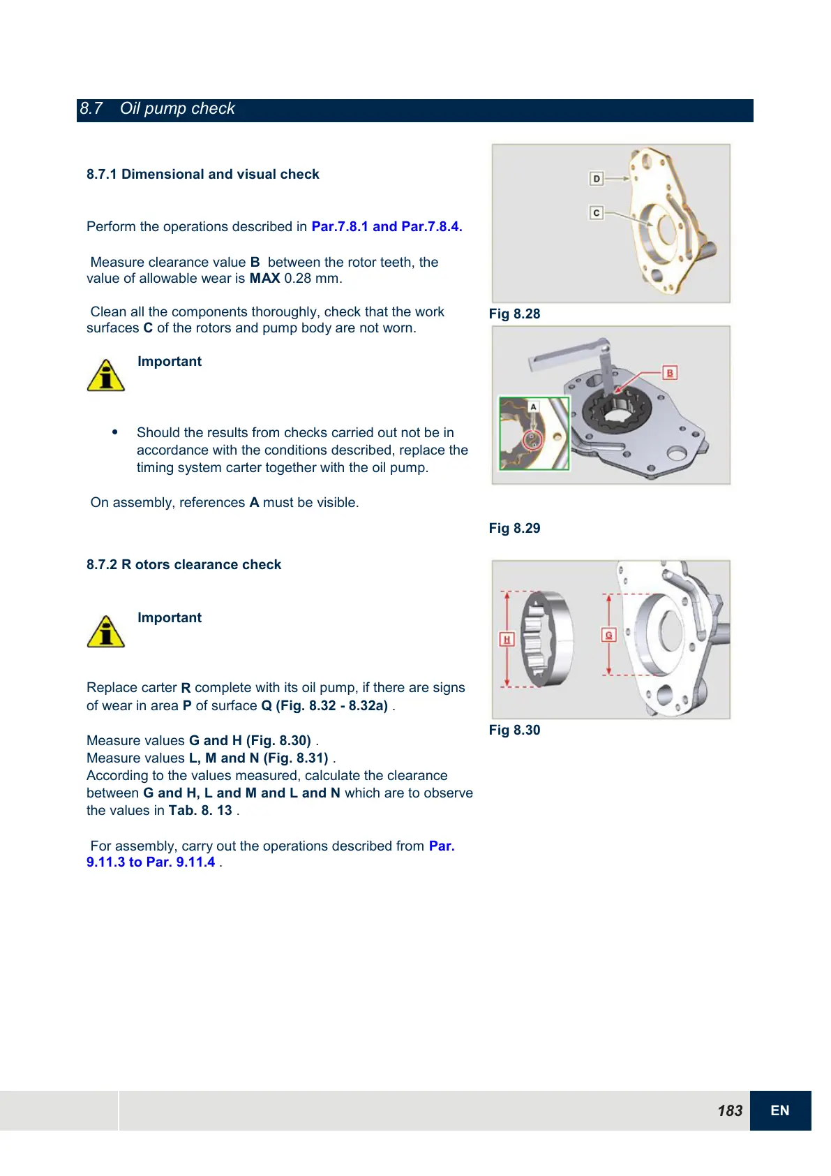
Measure values
G and H (Fig. 8.30)
.
Measure values
L, M and N (Fig. 8.31)
.
According to the values measured, calculate the clearance
between
G and H, L and M and L and N
which are to observe
the values in
Tab. 8.
13
.
For assembly, carry out the operations described from Par.
9.11.3 to Par. 9.11.4 .

 Loading...


