EasyManua.ls Logo

Kohler KDI 1903 TCR

Kohler KDI 1903 TCR
315 pages
To Next Page IconTo Next Page
To Previous Page IconTo Previous Page
Loading...
EN
2.12 Intake and exhaust circuit
2.12.1 Turbocharger
The turbocharger is controlled by means of exhaust gas that
activates the turbine.
Important
See Par 2.18 .
Tab 2.31
POS.
DESCRIPTION
1
Air intake hose
2
Air compression volute
3
Turbo charger central body
4
Turbine housing with Waste Gate valve
5
Gas exhaust flange
6
Waste Gate control valve hose
7
Waste Gate valve control actuator
8
Waste Gate control valve linkage
9
Engine crankcase breather
10
Air compressed flow hose to intercooler
11
Oil drain pipe
12
Turbo charger lubrication pipe
Fig 2.27
2.12.2
ATS device
2.12.2.1 DOC
The DOC is a device to filter exhaust gas by means of its
oxidation.
Internally, it is composed of hundreds of small ducts that enable
the passage of exhaust gas.
It contains precious metals (platinum, palladium, iridium).
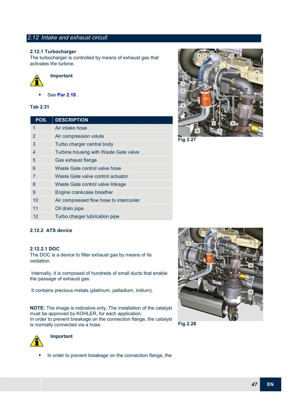
NOTE: The image is indicative only. The installation of the catalyst
must be approved by KOHLER, for each application.
In order to prevent breakage on the connection flange, the catalyst
is normally connected via a hose.
Important
In order to prevent breakage on the connection flange, the
Fig 2.28

Table of Contents

Other manuals for Kohler KDI 1903 TCR

Related product manuals