not been removed, rotate the
crankshaft positioning the reference BQ located on the
target wheel in correspondence of the speed sensor, as
shown in Fig. 9.60b .
If the engine is painted or protected with clear paint,
replace the fastening screws BE .
1.
Position the rocker arm pin assembly BB on the head F ,
respecting the plug BC on the head using the holder
indicated AV .
2.
Check the correct positioning of all the rocker arms and
the u-bolt control valves (detail BD ). House the tappet in
the seat of the rocker arms control rod.
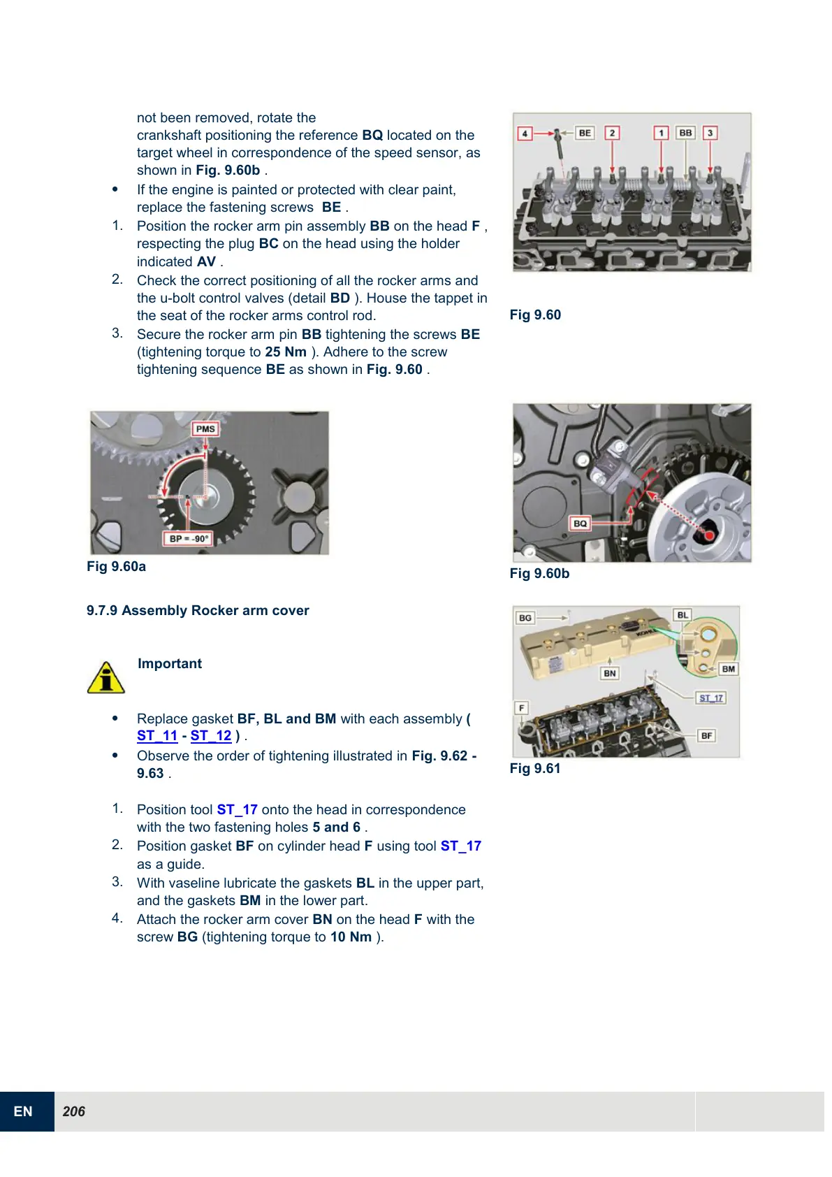
3.
Secure the rocker arm pin BB tightening the screws BE
(tightening torque to 25 Nm ). Adhere to the screw
tightening sequence BE as shown in Fig. 9.60 .
9.7.9 Assembly Rocker arm cover
Important
Replace gasket BF, BL and BM with each assembly (
ST_11 - ST_12 ) .
Observe the order of tightening illustrated in Fig. 9.62 -
9.63 .
1.
Position tool ST_17 onto the head in correspondence
with the two fastening holes 5 and 6 .
2.
Position gasket BF on cylinder head F using tool ST_17
as a guide.
3.
With vaseline lubricate the gaskets BL in the upper part,
and the gaskets BM in the lower part.
4.
Attach the rocker arm cover BN on the head F with the
screw BG (tightening torque to 10 Nm ).

 Loading...


