40
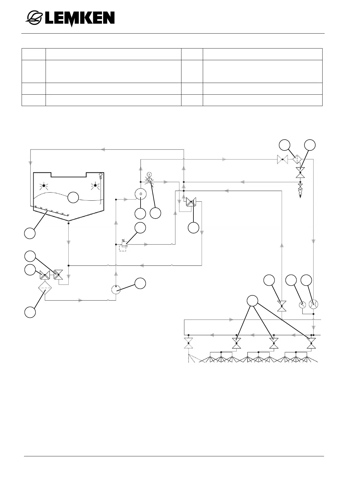
Selection valve, spray pump
Switchover valve spraying agent /
clean water
Drain valve pressure filter
4.5.2 Description of the spraying process up to 3500 l
During the spraying process, the spray pump (H) draws the spraying fluid from the
main tank (7) via the switching valve (C), the selection valve (A) and the suction
filter (9). The spraying fluid is then pumped to the nozzles via the diverting valve
(D) and the pressure filter (3).
The control valve (2) can be used to control the metering of the distribution rate.
The control valve is operated by the control unit and allows the spraying fluid not