CSP−900RMM−2 MD Helicopters, Inc.
Rotorcraft Maintenance Manual
Page 606
Revision 36
67-10-00
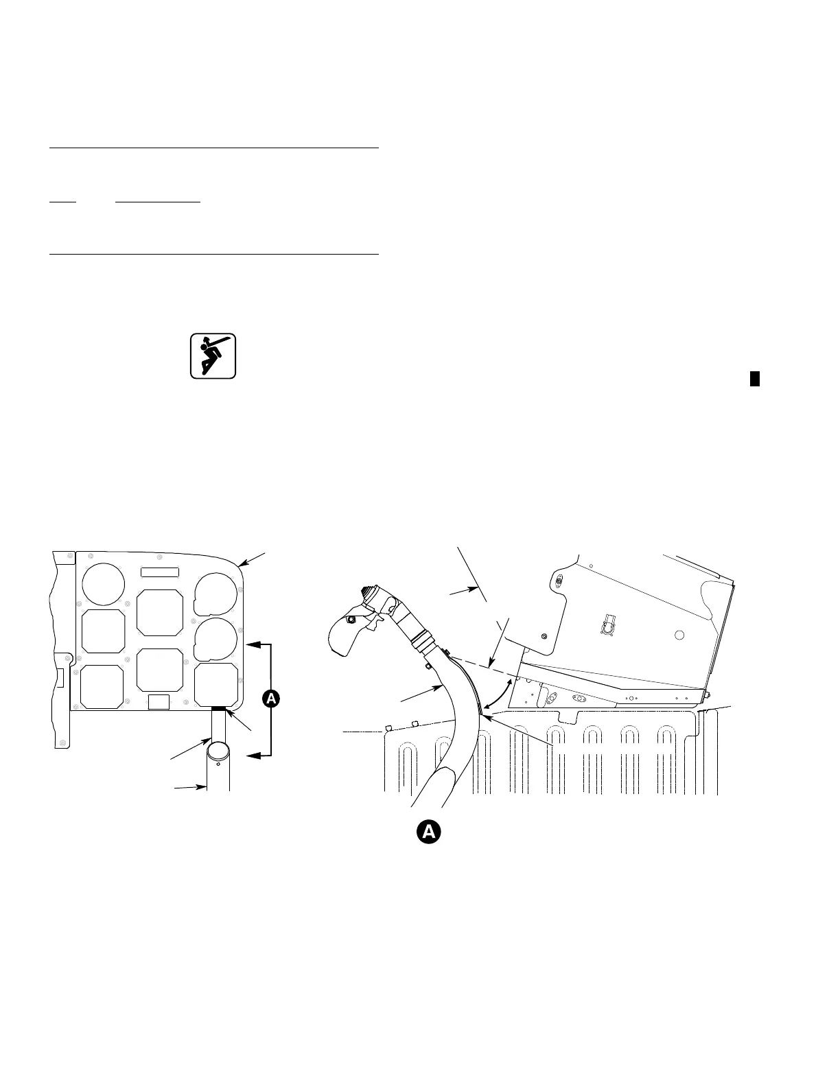
E. Cyclic Stick In Center Position Procedure
(Ref. Figure 601)
Special Tools
(Ref. CSP−SPM)
Item Nomenclature
T2001 Hydraulic Mule
T2002 Ground Power Unit
NOTE: Do this procedure when the rotorcraft is
serviced, in maintenance, or shutdown.
Moving Flight Controls
(1). Apply 1000 psig (6894.8 kPa) hydrau
lic pressure to Hydraulic System
Number 1 with hydraulic mule (T2001)
(Ref. Section 29-00-00).
(2). Apply external electrical power with
ground power unit (T2002) (Ref.
CSP-900RMM-3).
NOTE:
Cyclic stick must be in center position
both laterally and longitudinally.
Do this procedure while sitting in the pi
lot crew seat.
(3). Detach the bottom of cyclic stick center
position strap (1).
(4). Extend cyclic stick center position strap
(1) forward until it touches instrument
panel (3) cyclic stick center position
placard (2).
(5). Strap (1) must be fully extended, in line
with placard (2), and touch placard (2).
(a). If necessary, move cyclic stick (4).
(6). Attach the bottom of cyclic stick center
position strap (1).
(7). Remove hydraulic pressure (ref. Section
29-00-00).
(8). Remove external electrical power (ref.
CSP-900RMM-3).
9G67−040A
2
3
VIEW LOOKING FORWARD
(CYCLIC GRIP REMOVED FOR CLARITY)
1 (STOWED POSITION)
REF. 1
(EXTENDED POSITION)
4
VIEW LOOKING INBOARD
FROM RIGHT SIDE
REF. 3
REF. 1
(EXTENDED
POSITION)
REF. 4
1. CYCLIC STICK CENTER POSITION STRAP
2. CYCLIC STICK CENTER POSITION PLACARD
3. MAIN INSTRUMENT PANEL
4. CYCLIC STICK
Figure 601. Cyclic Stick In Center Position Procedure