CSP−900RMM−2 MD Helicopters, Inc.
Rotorcraft Maintenance Manual
Page 402
Revision 34
21-50-00
(c). Do the Hose and Tube Internal
Cleaning procedure (ref. CSP-SPM,
Section 20-20-00).
Oil, Lubricating (C106)
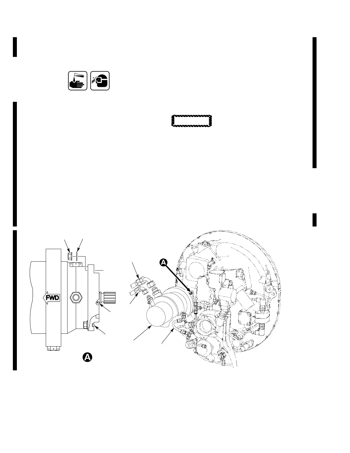
(3). Lubricate packings (8, 9) with lubricat
ing oil (C106).
(4). Install packings (8, 9) on compressor
(1).
(5). Install compressor (1) with nuts (6) and
washers (7).
(a). Torque nuts (6) 100 to 140 in-lb
(11.30 to 15.82 Nm).
(6). Connect drain hose (4).
(a). Torque both captive nuts of drain
hose (4) 50 to 65 in-lb (5.65 to 7.34
Nm).
(7). Connect inlet hose (3).
(a). Torque the fitting of inlet hose (3)
460 to 500 in-lb (51.97 to 56.49
Nm).
(8). Connect outlet hose (2).
(a). Torque the fitting of outlet hose (2)
230 to 260 in-lb (25.99 to 29.38
Nm).
(9). Connect Electrical Connector SP1 (5).
The receiver dehydrator must
be replaced each time the com
pressor is removed, or the AC system is
opened. An early failure of the compressor
can occur.
(10). Remove and replace the receiver
dehydrator (ref. Procedure 22.).
(11). Service compressor reduction gearbox
(ref. Section 12-00-00).
(12). Service AC system (ref. Section
12-00-00).
(13). Close Access Panel R210 (ref. Section
06-00-00).
7
6
8
9
4
1
5
2
3
9G21−008B
1. AC COMPRESSOR (REF. IPL, 21−50−00, FIG. 3)
2. OUTLET HOSE (HIGH−PRESSURE)
3. INLET HOSE (LOW−PRESSURE)
4. DRAIN HOSE (COMPRESSOR DRAIN)
5. ELECTRICAL CONNECTOR SP1
6. NUT
7. WASHER
8. PACKING
9. PACKING
Figure 401. Removal and Installation of the Compressor (Right Engine)
CAUTION
 Loading...


