CSP−900RMM−2 MD Helicopters, Inc.
Rotorcraft Maintenance Manual
Page 102
Original
26-10-20
Table 101. Deck and Engine Area Fire/Overheat Detection System Troubleshooting (Cont.)
Fault Ref. SectionCorrective ActionProbable Cause
SENSFALT=12 On IIDS
alpha/numerical display. (See
Notes)
Faulty fire/overheat
detection control unit.
Remove and replace
fire/overheat detection control
unit
26−10−20
NOTES:
(1) The Fire/overheat detection system is automatically self tested by the Integrated Instrument Display
System (IIDS) when electrical power is applied. Additionally if a manual test is required, a built in fault
detection circuit wired into a press to test DISP key located on the IIDS front panel may be used. By
depressing and holding the DISP key 3 to 5 seconds all liquid crystal display (LCD) illuminate. When the
DISP key is released a 1 second flash from each (FIRE) WARNING indicator indicates a normal
functional system. No flash of (FIRE) WARNING indicates a fault in the system that failed to flash. Each
is connected to a separate fire control unit circuit test through the IIDS.
ACFTFALT = 1 Transmission fire detect fault, ACFTFALT =2 Left engine fire fault, or
ACFTFALT =3 Right engine fire fault will appear on IIDS fault log alpha/numerical display for the failed
detection system.
E
E
GS306-K
GS304-F
FIRE/OVERHEAT
CONTROL
(TRANSMISSION DECK)
J1
P370
J477
J475
J3 J2
ELECTRICAL LOAD CENTER
P377
P374
P128J2
P102J2
A
B
14M
15N
16P
CB3
XMSN FIRE
60
E
B
D
H
J
A
G
K
F
C
2
59
58
CALIBRATION RESISTOR
EXTERNAL CALIBRATION
RTN
LOOP A
LOOP B
PWR GND
CHASSIS GROUND
28VDC
TEST
FAULT
FIRE
XMSN TEST
XMSN FIRE FAULT
XMSN FIRE
LOOP
5A
BAT
BUS
T
T
TT
TT
A601 900 CONFIG
A2
IIDS
A602
A105
W123
W124
W124
W124
9G26−009B
CIRCUIT BREAKER PANEL
FDL1
FIRE DETECTION CABLE
(TRANSMISSION DECK)
P2
P1
P128J2
2
5A
BAT
BUS
CB4
XMS
N
FIRE
L. ESS BUS
A601 902 CONFIG
CIRCUIT BREAKER PANEL
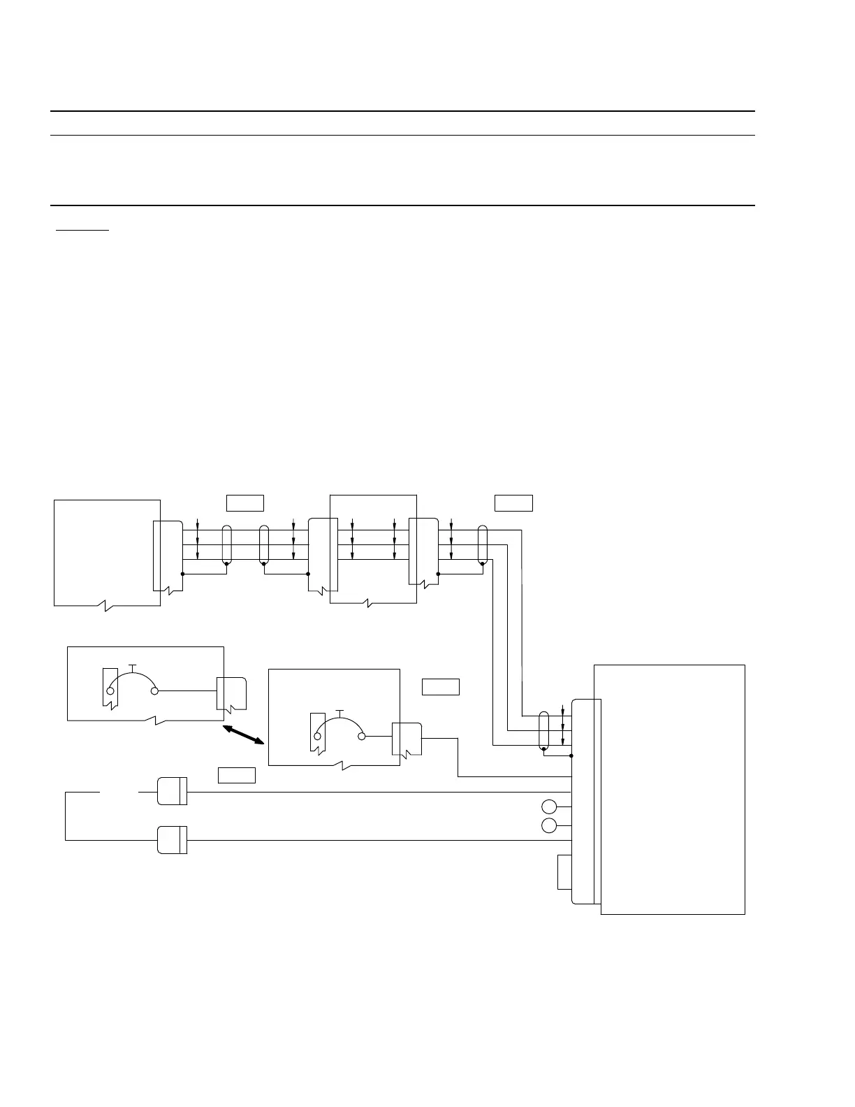
Figure 101. Transmission Deck Fire/Overheat Detection System Wiring Diagram