10. Navigation and guidance system
MiR250 Hook User Guide (en) 01/2023 - v.1.2 ©Copyright 2021-2023: Mobile Industrial Robots A/S. 106
Once the local path is determined, the robot computer derives the desired rotational velocity of
each drive wheel to make the robot follow the local path and sends the desired velocities for each
motor to the motor controllers—see "Motor controller and motors" on page116.
10.5 Obstacle detection
The robot detects obstacles continuously while driving. This enables the robot to use the local
planner to drive around obstacles and to determine the robot's current position on the map.
• The safety laser scanners
• The 3D cameras
• The proximity sensors
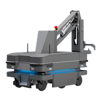
What a human sees
A chair placed in the corner
of a room is detectable by
the robot.
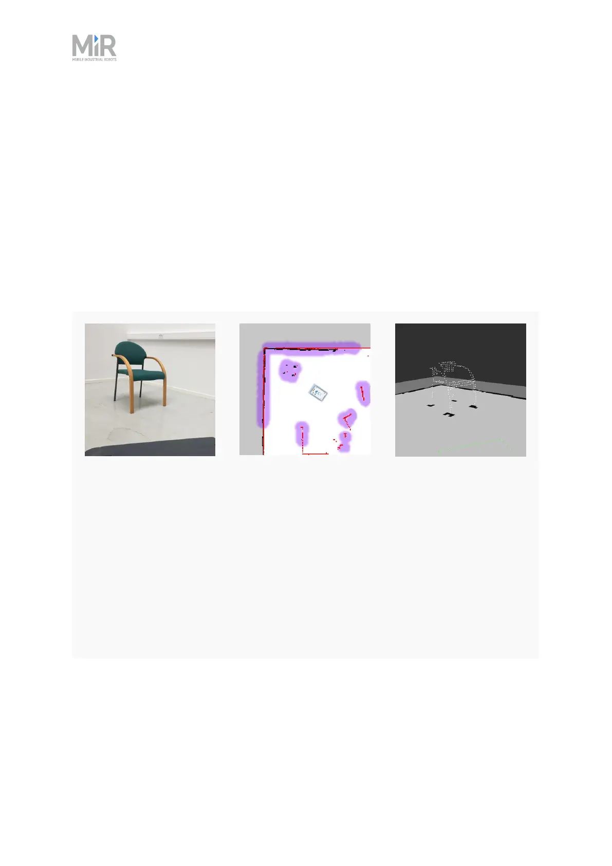
What the laser scanners
see
In the robot interface, the
red lines on a map are
obstacles detected by the
laser scanners, and the
purple clouds are an
aggregate of the 3D
camera and laser scanner
data. The scanners only
detect the four legs of the
chair.
What the 3D cameras
see
The 3D cameras detect
more details of the chair
when the robot gets close
enough to it.This view
cannot be seen in the
robot interface.