Installation
130
Mitel 415/430 as of R4.1
syd-0580/1.2 – R4.1 – 08.2016
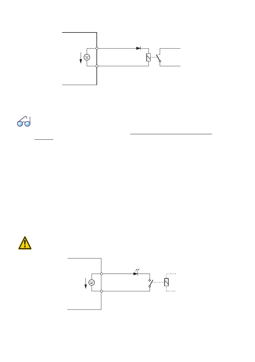
[1] The diode is necessary, in order to avoid unwanted voltages at the control output during the the start-up phase of
the communication server.
Fig. 55 Connection for FXS mode: Control output
See also
Besides the control outputs on FXS interfaces control outputs on ODAB cards can also be used
to control external devices and equipment (see "Equipment on the ODAB options card",
page 138).
FXS mode: Control input
If FXS interfaces are configured as control inputs, one or more of the switch groups
can be switched between Positions 1, 2 and 3. An external switch or a relay is con-
nected for this purpose. An LED can be connected to the circuit to indicate the switch
state. The no-load voltage is 24 VDC; the current is limited to 25mA.
The permissible switch and loop resistances are as follows:
• Active state (On): < 1 kΩ
• Passive state (Off): > 4 kΩ
There are no special requirements for the cables.
Warning
Control inputs must have a floating connection.
Fig. 56 Connection for FXS mode: Control input
a
b
[1]
24 VDC
max. 25mA
FXS interface
a
b
24 VDC
25mA
FXS interface