Chapter 5: Installation
Installing a Processor Expansion Card (PEC-1)
Page 5-40 Inter-Tel
®
5000 Installation Manual – Issue 2.4, May 2008
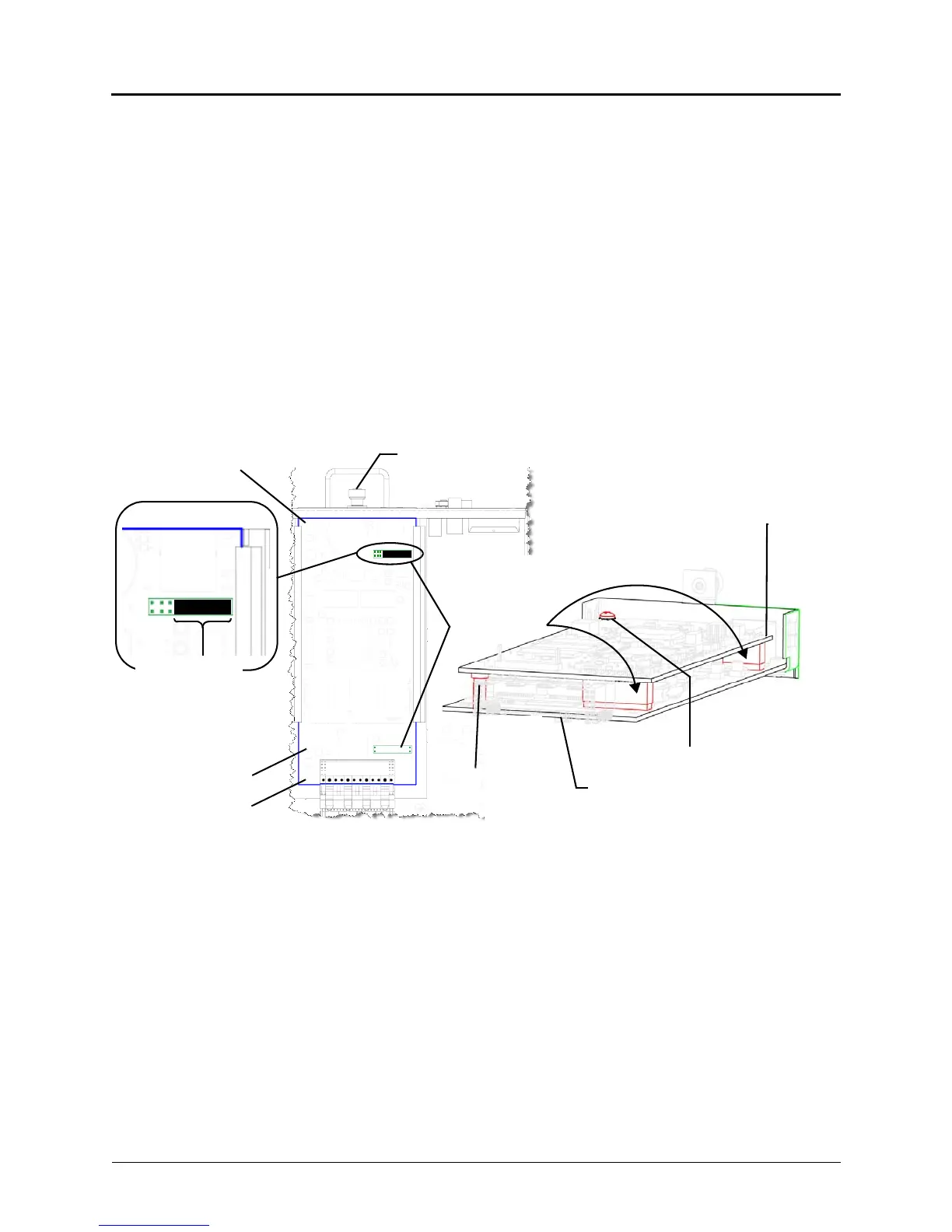
6. Mount the PEC-1 onto the processor module. See Figure 5-17 as a guide.
a. Carefully align the PEC-1 mount points and the stand-off mount points.
b. Gently press the smaller end of the standoff onto the processor module while
aligning the screw mount point over the hexagon-shaped metal standoff and the PEC
mount points. Do not force the card onto the module.
7. Secure the PEC-1 to the processor module using the supplied screw (located in a small
plastic bag attached to the PEC-1 anti-static bag). This screw attaches to the hexagon-
shaped metal stand-off installed in step 5c on page 5-39. Do not overtighten this screw.
Insert the processor module into the chassis as described in the procedure “Installing a
Processor Module (PM-1)” on page 5-36.
8. Check that all cables are connected and plug in the AC power cord. The system boots
and when finished, it displays Inter-Tel 5000 on the LCD panel. This indicates the system
is ready to be programmed.
9. Refer to the Inter-Tel 5000 Features and Programming Guide (part no: 580.8006) for
information to load the license file. You can then program the additional IP resources.
Figure 5-17. Expansion Card Upgrade (Inter-Tel CS-5200 to CS-5400)
Processor
Screw to secure metal
standoff (support) to
expansion module and
Module
Processor
Processor
Expansion Card
Chassis Back
Processor
Expansion Card
mount points
Module
Plastic
SDRAM Module
strap before installing
the expansion card.
See the preceding
processor module
standoff (support)
Processor module-to-chassis fastener
Plastic standoff
mount location
Remove this
Metal standoff
mount location
IMPORTANT note