Chapter 5: Installation
Installing Modules in the DEI
Page 5-74 Inter-Tel
®
5000 Installation Manual – Issue 2.4, May 2008
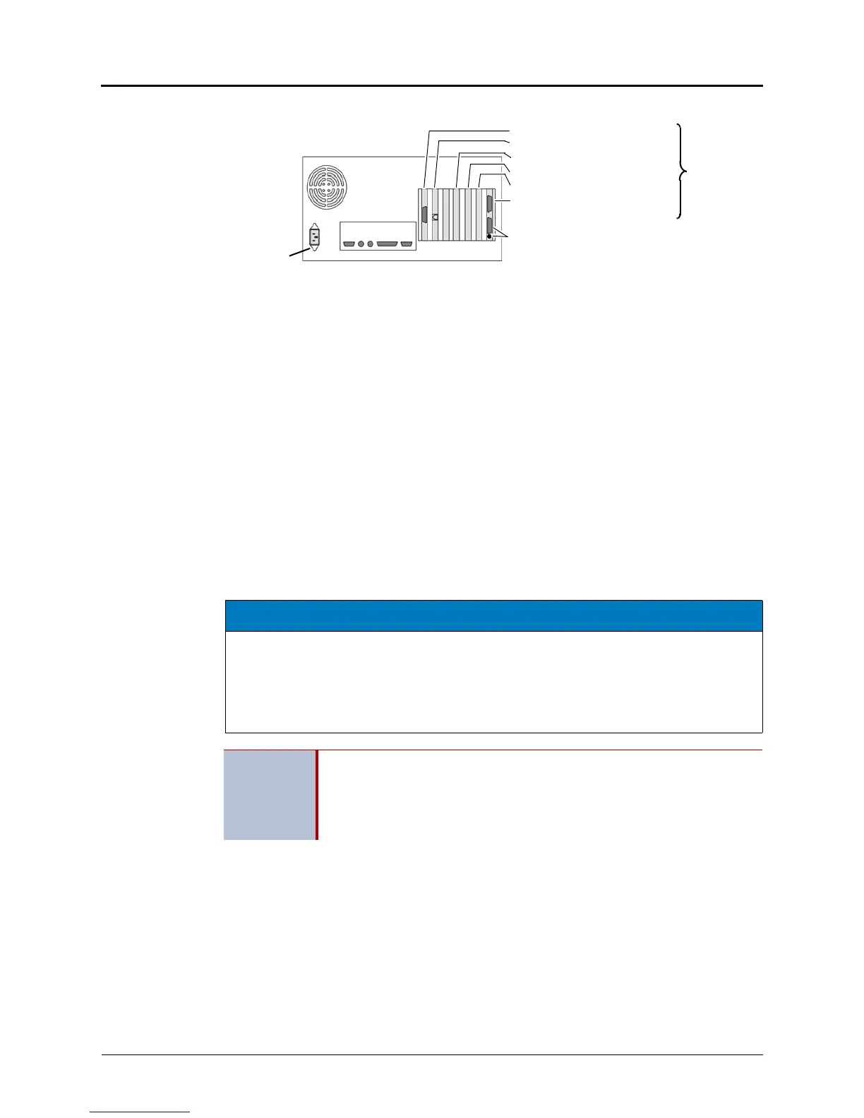
Figure 5-39. Back of Assembled External Voice Processing PC
Installing Modules in the DEI
Each DEI chassis attached to the Inter-Tel CS-5200/5400/5600 Base Server chassis may be
equipped with 16-port Digital Endpoint Modules (DEM-16) and/or eight-port Single Line Modules
(SLM-8). Installation instructions for the DEM-16 and the SLM-8 follow, and an example of
DEM-16 and SLM-8 circuit mapping appears in Figure 5-43 on page 5-77.
Installing a Digital Endpoint Module (DEM-16)
Each DEM-16 supports up to 16 digital endpoints. Digital endpoints include Inter-Tel digital
endpoints and Inter-Tel Single-Line Adapters (SLA). This section provides the procedures you
need to install the DEM-16. Procedures for installing digital endpoints and SLAs appear in the
following section. For a feature description of the DEM-16, see “Endpoints and Endpoint
Features” on page 6-13.
Each DEI chassis accepts up to three DEM-16s to provide digital capability on the Inter-Tel
5000 platform. See the Specifications and Product Description chapters for additional module
information.
To install a DEM-16:
1. Using a properly terminated, anti-static wrist strap, remove the module from the
protective anti-static bag. See Figure 5-22 on page 5-46 for a DEI chassis and DEM-16
example for the remaining steps in this procedure.
2. Insert the module carefully so that it aligns with the rails inside the chassis, then gently
slide the module into the chassis until it stops. Do not use force.
3. Tighten the fastener at the top of the module, securing the module to the chassis. Do
not over-tighten this fastener.
4. Continue to “Verifying and Securing Cable Connections” on page 5-33.
Power Cable Connector
not used
Video Card
Network Interface Card
1ST VPC
2ND VPC
Optional FAX card
To Inter-Tel 5000 Base Server
Sample
or DEI (part no. 813.1806)
Depending on the
PC model used, the
card slot arrange-
ment and connector
locations shown at
right could be differ-
ent.
Card Slot
Arrangement
NOTICE
Electrostatic Discharge (ESD). Inter-Tel 5000 modules and components are static-
sensitive. When working with the modules, use a properly terminated anti-static wrist strap.
Any static charge (no matter how small) must be discharged from the body before touching
the modules or other components. The warranty for this equipment does not cover damage
caused by static or mishandling. Modules or components damaged in such a manner will not
be replaced.
IMPORTANT
The DEM-16 can be removed with power on; however, any calls on those
circuits will be dropped.
DEM-16s can reside in any bay, but DB Programming will need to be
changed if you move a module (that was previously programmed) into a
different bay location.