Chapter 5: Installation
Single T1/E1/PRI Module LED Summary
Inter-Tel
®
5000 Installation Manual – Issue 2.4, May 2008 Page 5-47
Single T1/E1/PRI Module LED Summary
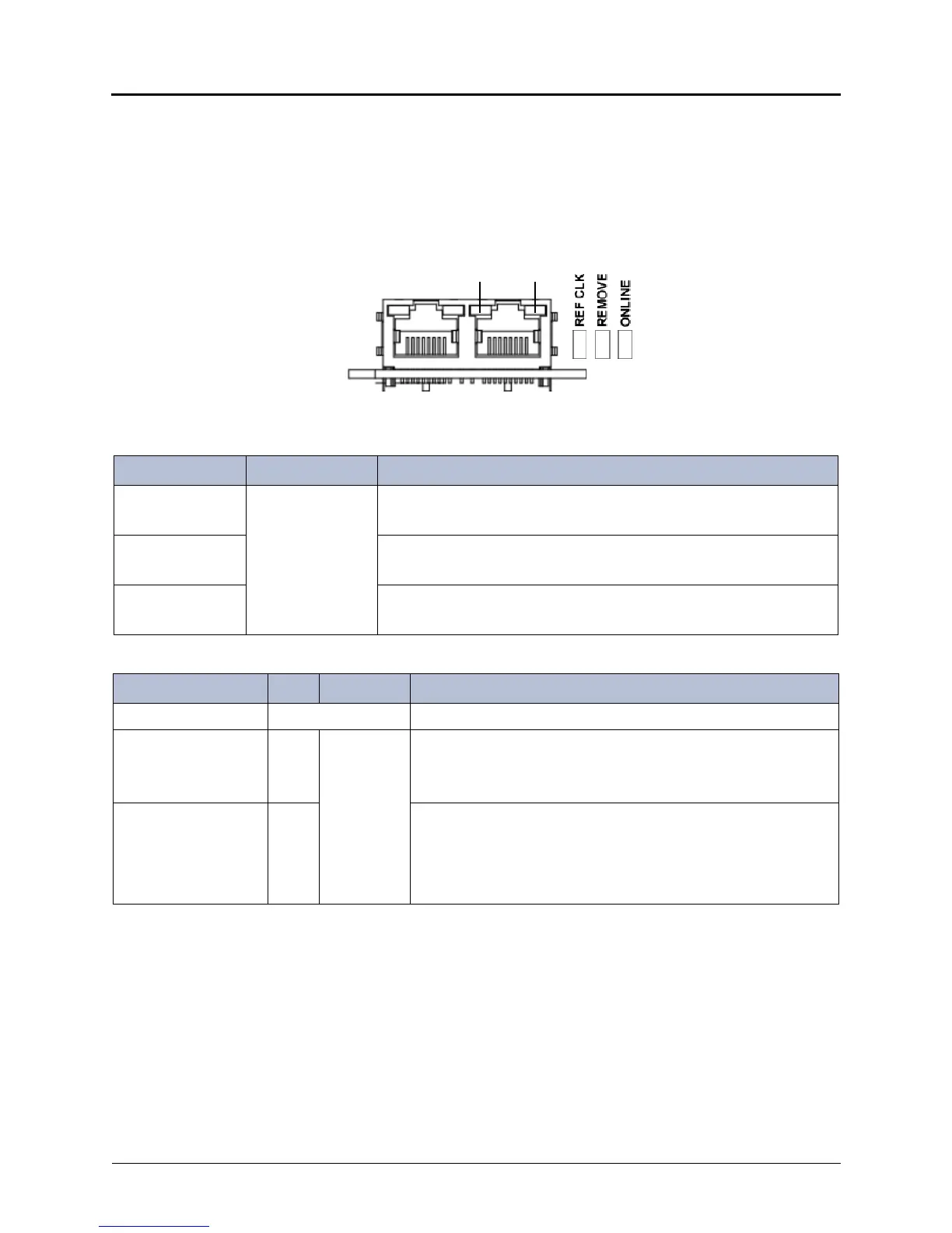
The single T1/E1/PRI module has a total of 7 LEDs (two unused) on the faceplate to indicate
module status. The LEDs are contained in two separate locations: 3 LEDs to the right side of
the module faceplate, and 2 green LEDs integrated into each RJ-45 connector.
These LEDs are described in Figure 5-23 and in tables 5-5 and 5-6 below.
Figure 5-23. Single T1/E1/PRI Module Faceplate LED Summary
12
RJ–45 Green LEDs
LED Indicators
Test Port Span
Table 5-5. Single T1/E1/PRI Module LED Summary — 3 LEDs
LED Name Color Indication
REF CLK Green ON: Span provides the reference clock for the system.
OFF: Span does not provide the reference clock for the system.
REMOVE ON: Board is safe to remove.
OFF: Board is not ready to be removed
ONLINE ON: Board is online and functioning normally.
OFF: Board is not online.
Table 5-6. Single T1/E1/PRI Module LED Summary — RJ-45 LEDs
LED Name LED Color Indication
Test port LEDs N/A Not used
SYNC
(synchronization and
alarm status)
1 Green Solid green: Stable state.
Blinking green: Initial trouble state or clearing trouble state.
OFF: Stable error state or span is disabled/not active.
MSTR (reference
clock)
2 Green ON: Follows the span configuration as programmed in the
database. The LED is on if the port/span is programmed for
“Master for Private Network,” as selected in the Reference Clock
List programming.
OFF: Span does not provide the reference clock for the system.


 To Next Page