Chapter 5: Installation
Physical Interfaces
Inter-Tel
®
5000 Installation Manual – Issue 2.4, May 2008 Page 5-105
Physical Interfaces
See the sections that follow for information on the supported endpoint physical interfaces to the
system. See page 5-101 for the installation procedure. See page 5-110 for information about
wall-mounting the endpoints.
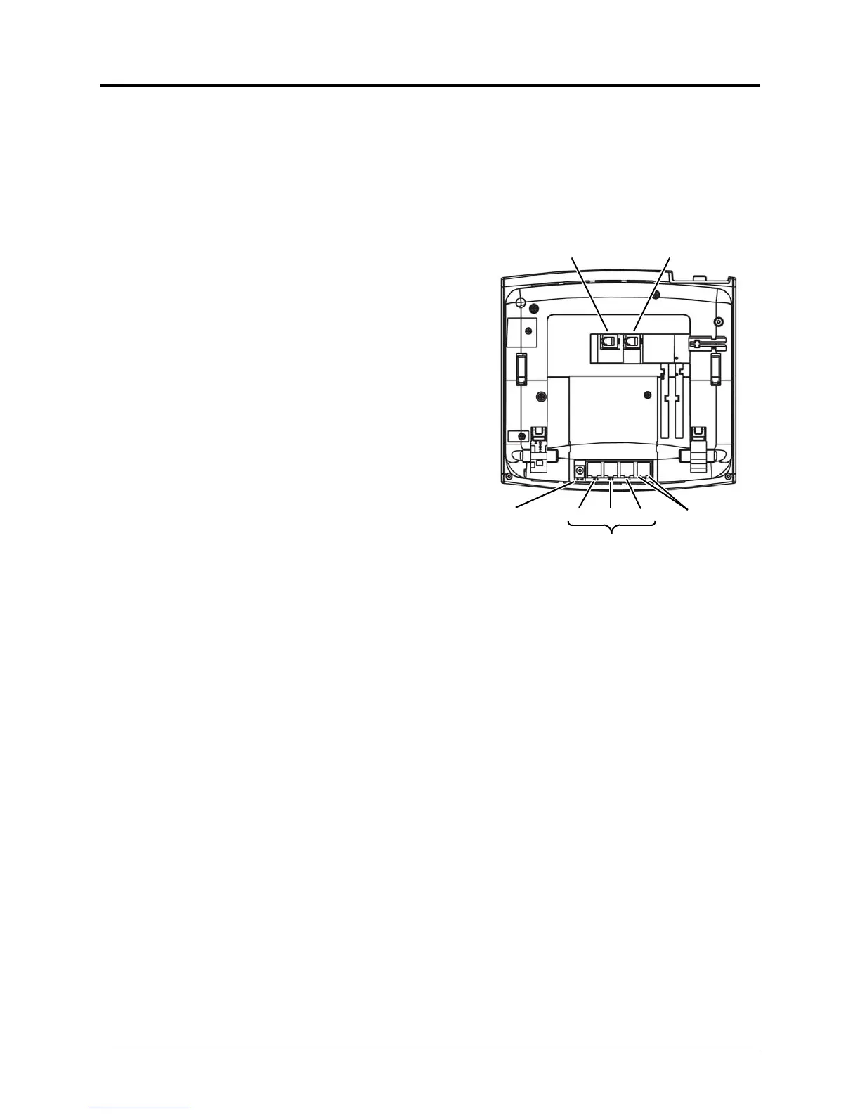
Model 8660
The Model 8660 is supported by both
10Base-T and 100Base-TX interfaces, but
not 100Base-T4, which uses four pairs of
wires. See the illustration at right.
The Model 8660 includes the following
connections:
• LAN/POWER Jack: Connects to a
network hub or a switch and gets
power from pins 7 and 8.
• POWER Jack: Connects to a 24 VDC
external power supply. Use only one
power source to connect the power
supply.
• PC 1-3 Ports: Connect to PCs or any
other Ethernet devices. The speeds
on single uplink and three downlink
ports are independent from each
other and auto-negotiable.
• Handset Jack: Connects to a
handset.
• Headset Jack: Connects to a
headset.
• LEDs: There are two indications on each port:
o Link Status: When the link is valid, the green LED on the left side of the port is lit.
When there is receive or transmit activity on the link, this LED flashes.
o 10/100 Mbps: When the link is connected at a speed of 100 Mbps, the green LED on
the right side of the port is lit. The Inter-Tel 5000 platform operates only on 100Base-T
LANs.
For information about programming a Model 8660, refer to the Programming chapter in the
Inter-Tel 5000 Features and Programming Guide (part no: 580.8006).
24VDC PC 3
PC 2 LEDs
(Downlink RJ-45)
Back
HEADSET Jack
HANDSET Jack
PC 1
POWER
Model 8600