Chapter 5: Installation
Installing a Four-Port Single Line Module (SLM-4)
Page 5-50 Inter-Tel
®
5000 Installation Manual – Issue 2.4, May 2008
Installing a Four-Port Single Line Module (SLM-4)
This section provides specifications, drawings, and procedures needed for installing an SLM-4,
part no. 580.2100.
Installing an SLM-4 consists of inserting the module into an empty bay on the back side of an
Inter-Tel CS-5200/5400/5600 Base Server and assigning the module to the Uninstalled bay
through DB Programming. You can then program up to four single line endpoints on the module
ports. See Figure 5-25. Because the Auto Equip feature does not apply when installing an SLM-
4, the module must be manually programmed in the system before it can be used.
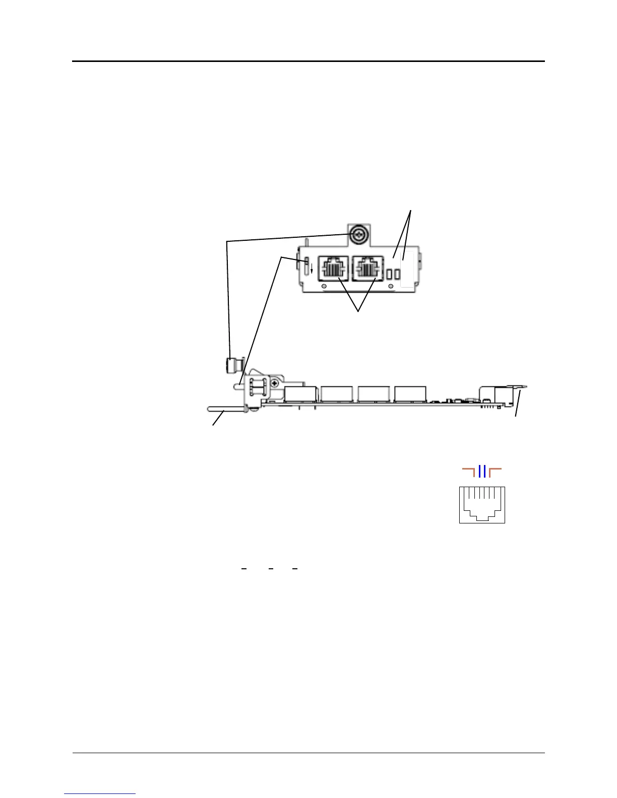
Figure 5-25. Parts of the SLM-4, Front and Side Views
The pinout design for four-port and eight-port Single Line
Module jacks (SLM-4 and SLM-8) is the same. Each RJ-14
jack represents two single line ports for connecting single line
analog endpoints. The middle four pins in the RJ-14 connector
are wired in accordance with Uniform Service Order Code
(USOC) T568A specifications, as shown in the following
diagram.
To install the SLM-4 module in an Inter-Tel CS-5200/5400/
5600 Base Server:
1. Put on ESD (e
lectrostatic discharge)-protective gear and ground yourself.
2. In DB Programming, uninstall any module that may be in the bay where you want to
install the SLM-4.
3. Remove the physical module in accordance with the applicable procedure—trunk
modules require the REMOVE LED to be lit before the module can be safely removed.
4. Insert the SLM-4 module into the empty bay. The green LED labeled ONLINE
illuminates, indicating that the new hardware has been detected and the Single Line (SL)
application is running.
Module Handle
Latch
SLM 4
PORTS 1-2 PORTS 3-4
REMOVE
ONLINE
PUSH
TO
REMOVE
Module
Status LEDs
Backplane
Seating Guides
Single Line Ports
Fastening
Screw
Lever
1 2 3 4 5 6
T1 1R
T2
2R
T1–R1 = Port 1 Tip and Ring
T2–R2 = Port 2 Tip and Ring