Chapter 5: Installation
Installing DID Trunks on an SLA (USA Only)
Inter-Tel
®
5000 Installation Manual – Issue 2.4, May 2008 Page 5-133
Installing DID Trunks on an SLA (USA Only)
Connect the Direct Inward Dialing (DID) trunks to the Single-Line Adapters as outlined below.
See Figure 5-57 on page 5-133. DID trunks are also supported through T1 circuits. In addition
to DID trunks, SLAs can also be used to install single line endpoints, playback devices, and off-
premises extension (OPX) stations. Any combination using the two ports on the SLA is possible.
For a diagram, see Figure 5-58 on page 5-134.
1. Mount one four-conductor modular jack assembly next to each telephone company RJ
jack.
2. For each modular jack assembly mounted in step 1, mount a corresponding four-
conductor modular jack assembly near the SLA location.
3. To connect the modular jack assemblies mounted in steps 1 and 2:
a. Run one-pair cable between the corresponding modular jack assemblies.
b. Wire each end of the one-pair cables onto their respective modular jack assemblies.
For a wiring diagram, see Figure 5-57 on page 5-133.
4. Plug one end of a two-pair, mod-to-mod line cord into each RJ jack and plug the other
end into the corresponding modular jack assembly beside it.
5. At the MDF backboard, plug one end of a two-pair mod-to-mod line cord into each
modular jack assembly. After programming the DEM-16 port, insert the plug into the
Circuit 1 or Circuit 2 jack on the SLA, as applicable. See “Programming an SLA for Dual
DID Trunks” on page 5-134.
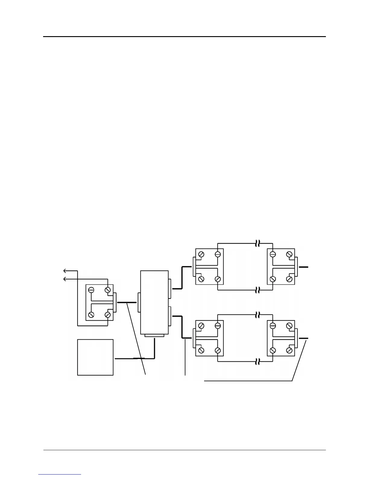
Figure 5-57. SLA Terminations for DID Trunks (USA Only)
Modular
Jack Assemblies
Endpoint Modular
Jack Assembly
SLA
AC Transformer
Standard Reversing
Mod-to-Mod Line Cord
To Telco
RJ
To Telco
RJ
TIP
RING
TIP
GY
BK
R
BK
R
RING
GY
G
R
R
G
Y
BK
BK
Y
GY
BK
R
RING
TIP
If a single line endpoint is located near the SLA, it can be plugged directly into the unit.
To
DEM
Block