Chapter 5: Installation
Dual T1/E1/PRI Module LED Summary
Page 5-44 Inter-Tel
®
5000 Installation Manual – Issue 2.4, May 2008
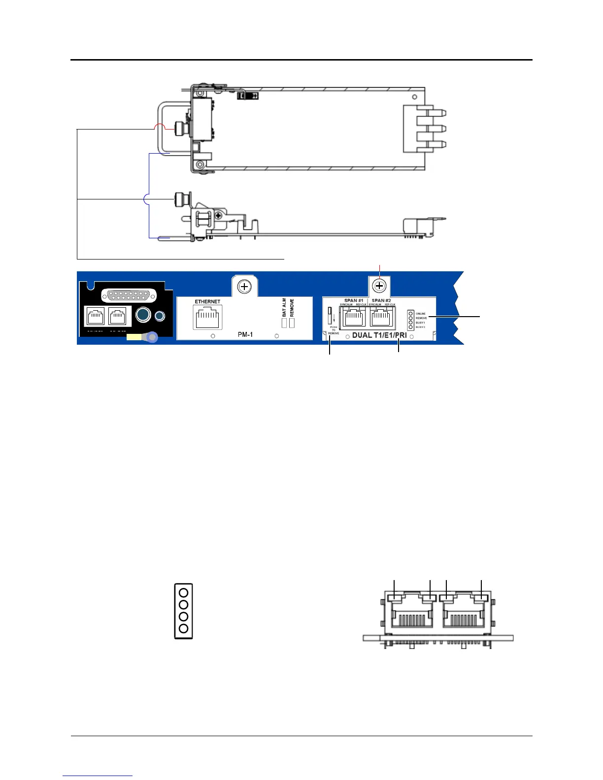
Figure 5-20. Dual T1/E1/PRI Module
To remove a dual T1/E1/PRI module:
1. Using a properly terminated anti-static wrist strap, loosen the fastener at the top of the
module (this fastener secures the module to the chassis).
2. Push down and hold the module release lever, and then when the REMOVE LED turns
green, grasp the module handle and carefully remove the module from the chassis.
Dual T1/E1/PRI Module LED Summary
The Dual T1/E1/PRI module has a total of 8 LEDs on the faceplate to indicate module status.
The LEDs are contained in two separate devices: a 4-LED stack, and 4 bi-color LEDs integrated
into the RJ-45 connector.
The LED stack has 2 green LEDs and 2 yellow LEDs. These LEDs are described in Figure 5-21
and in tables 5-3 and 5-4 on page 5-45.
Figure 5-21. Dual T1/E1/PRI Module Faceplate LED Summary
DUAL LS
DUAL SL
EXP
PAGE MOH
Chassis Back
Module Release Lever Dual T1/E1/PRI Module
Remove
Module to Chassis Fastener
Module LED
Module Handle
Top
Side
Online
Remove
Busy 1
Busy 2
1234
RJ–45 Red/Green LEDs
4-LED Stack Indicators
Span #1 Span #2