Chapter 5: Installation
Dual T1/E1/PRI Module LED Summary
Inter-Tel
®
5000 Installation Manual – Issue 2.4, May 2008 Page 5-45
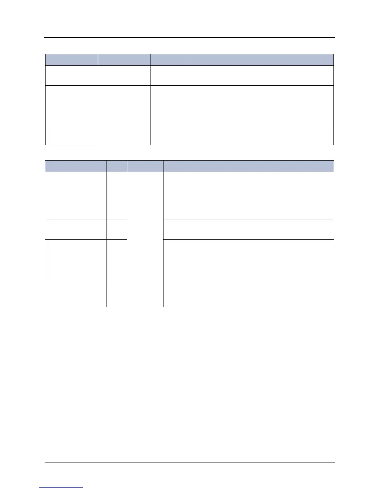
Table 5-3. Dual T1/E1/PRI Module LED Summary — 4-LED Stack
LED Name Color Indication
Online Green #1 ON: Board is online and functioning normally.
OFF: Board is not online.
Remove Green #2 ON: Board is safe to remove.
OFF: Board is not ready to be removed
Busy 1 Yellow #1 ON: One or more channels on the first span are active.
OFF: No channels on the first span are active.
Busy 2 Yellow #2 ON: One or more channels on the second span are active.
OFF: No channels on the second span are active.
Table 5-4. Dual T1/E1/PRI Module LED Summary — RJ-45 LEDs
LED Name LED Color Indication
SYNC/ALRM Span 1
(synchronization and
alarm status)
1Green or
Red
Solid green: Stable state.
Blinking green: Initial trouble state or clearing trouble state.
Solid red: Stable error state.
Blinking red: Clearing trouble state.
OFF: Span is disabled / not active.
REF_CLK Span 1
(reference clock)
2 Green ON: Span provides the reference clock for the system.
OFF: Span does not provide the reference clock for the system.
SYNC/ALRM Span 2
(synchronization and
alarm status)
3 Solid green: Stable state.
Blinking green: Initial trouble state.
Solid red: Stable error state.
Blinking red: Clearing trouble state.
OFF: Span is disabled / not active.
REF_CLK Span 2
(reference clock)
4 Green ON: Span provides the reference clock for the system.
OFF: Span does not provide the reference clock for the system.