Chapter 5: Installation
Installing a Processor Module (PM-1)
Inter-Tel
®
5000 Installation Manual – Issue 2.4, May 2008 Page 5-37
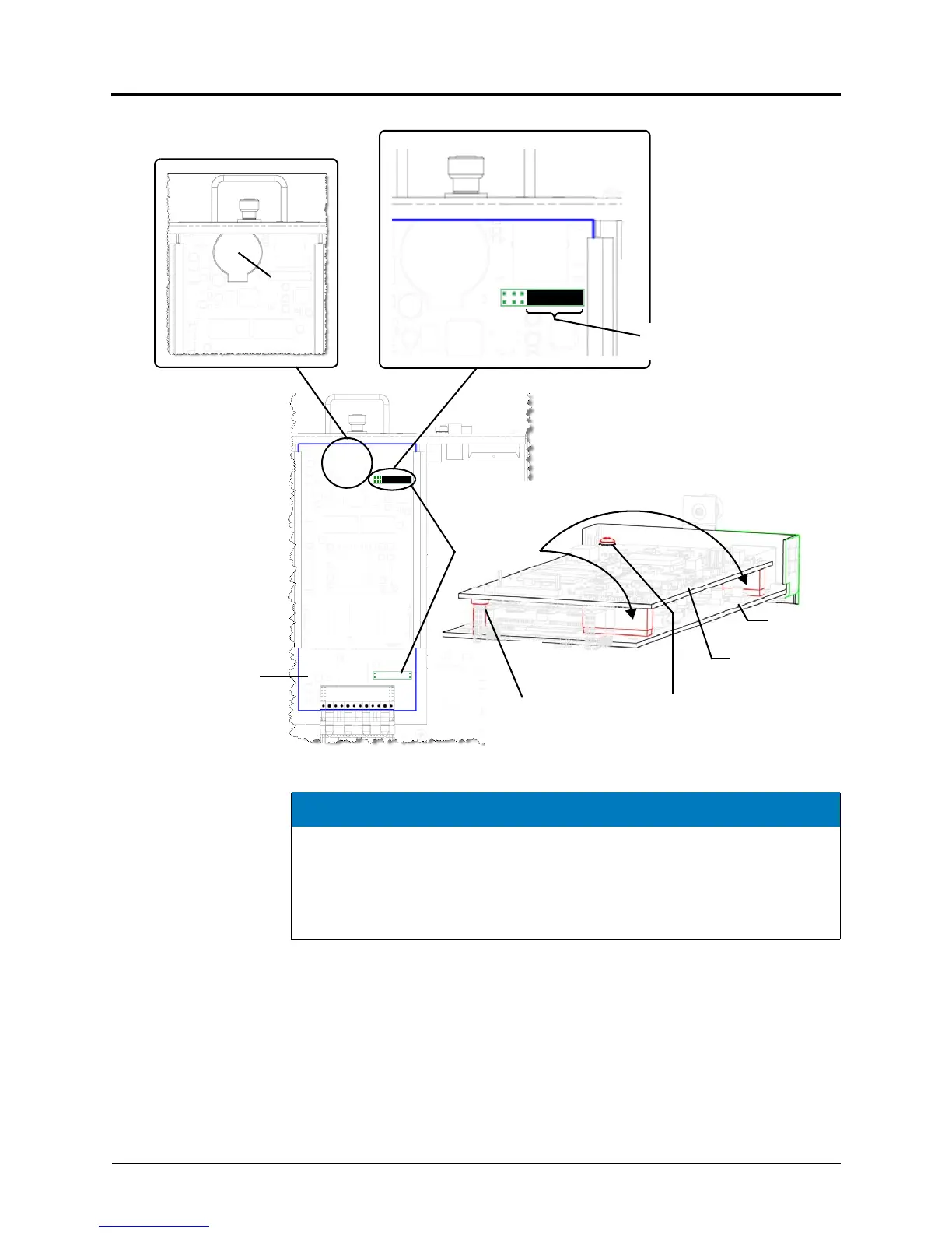
Figure 5-16. Components of a Processor Module (PM-1)
4. Insert the module carefully into the first bay (left side looking at the back of the chassis).
Make sure the module aligns with the rails inside the chassis, then gently slide the
module into the chassis until it stops. Do not use force.
5. Tighten the fastener at the top of the module, securing it to the chassis. Do not over
tighten this fastener.
6. If not adding any other modules, continue to “Installing the USB Security Key and Inter-
Tel Memory Card” on page 5-19. Otherwise, continue to “Installing a Two-Port Loop Start
Module (LSM-2)” on page 5-41.
Processor
Module
Processor
Processor
Expansion Card
Chassis Back
Processor
expansion card
mount points
Module
SDRAM
Module
Processor
Module
Battery
Top View
Read the NOTICE below.
This strap must be in place.
Screw to secure hexagon
metal standoff (support) to
expansion module and
processor module
Plastic
standoff (support)
NOTICE
System Inoperability. A strap covers pin 1 through pin 7 (far right in Figure 5-16).
This strap must be in place, unless using the processor expansion card (page 5-38). If
a system ever needs to function without the processor expansion card (for example,
replacing the expansion card), the strap will need to be put back on the processor
module. The standard processor module (Inter-Tel CS-5200) will not function without
the strap in place.