Chapter 5: Installation
Installing DEI Hardware
Inter-Tel
®
5000 Installation Manual – Issue 2.4, May 2008 Page 5-63
Installing DEI Hardware
This section describes DEI chassis and DEM-16 module installation.
Installing the DEI Chassis
To install the DEI chassis:
1. Install the chassis in the rack under the Inter-Tel CS-5200/5400/5600 Base Server. Allow
room below the chassis for future expansion (for example, a second DEI chassis or
optional Voice Processing system) and proper cooling. See Figure 5-1 on page 5-15,
Figure 5-33 on page 5-65, and Figure 5-39 on page 5-74 for examples.
There are external voice processing options available using the Voice Processing Unit
(VPU) or Enterprise
®
Messaging (EM). The optional VPU is a standalone Windows 2000
Server PC that can be rack mounted (recommended) or placed on a horizontal surface
(in proximity to the Inter-Tel CS-5200/5400/5600 Base Server). The EM unit is a
standalone Windows-based PC, similar in appearance to the VPU, that can also be rack
mounted (recommended) or installed on a horizontal surface.
2. Do not plug in the system AC power cable.
3. Continue to “Base Server Modules” on page 5-36.
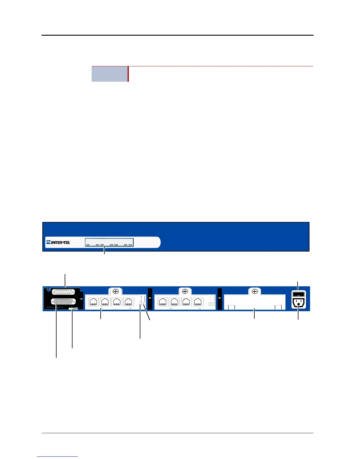
Figure 5-31. Example Inter-Tel DEI Chassis Front and Back View
IMPORTANT
Do not plug in any power cords until instructed to do so. Powering up the
system occurs later in the installation.
BAY 1
EXP 2
EXP 1
DEM-16
1 – 4 5 – 8 9 – 12 13 – 16
BAY 3
DEM-16
1 – 4 5 – 8 9 – 12 13 – 16
BAY 2
Power
To Inter-Tel 5000 Base Server
To optional External Voice Mail or 2nd DEI
DEI Chassis Back
DEI Chassis Front
Status Panel
Ground Lug (Earth ground)
DEM-16
Fuse
Module Bay
Cover*
Remove Module
Battery Alarm LED
LED
PWR MODULE 1 MODULE 2 MODULE 3
ON BUSY ON BUSY ON BUSY
(if 2nd DEI exists, then Voice Mail must be
attached to 2nd DEI)
BUSY
ONLINE
BUSY
ONLINE