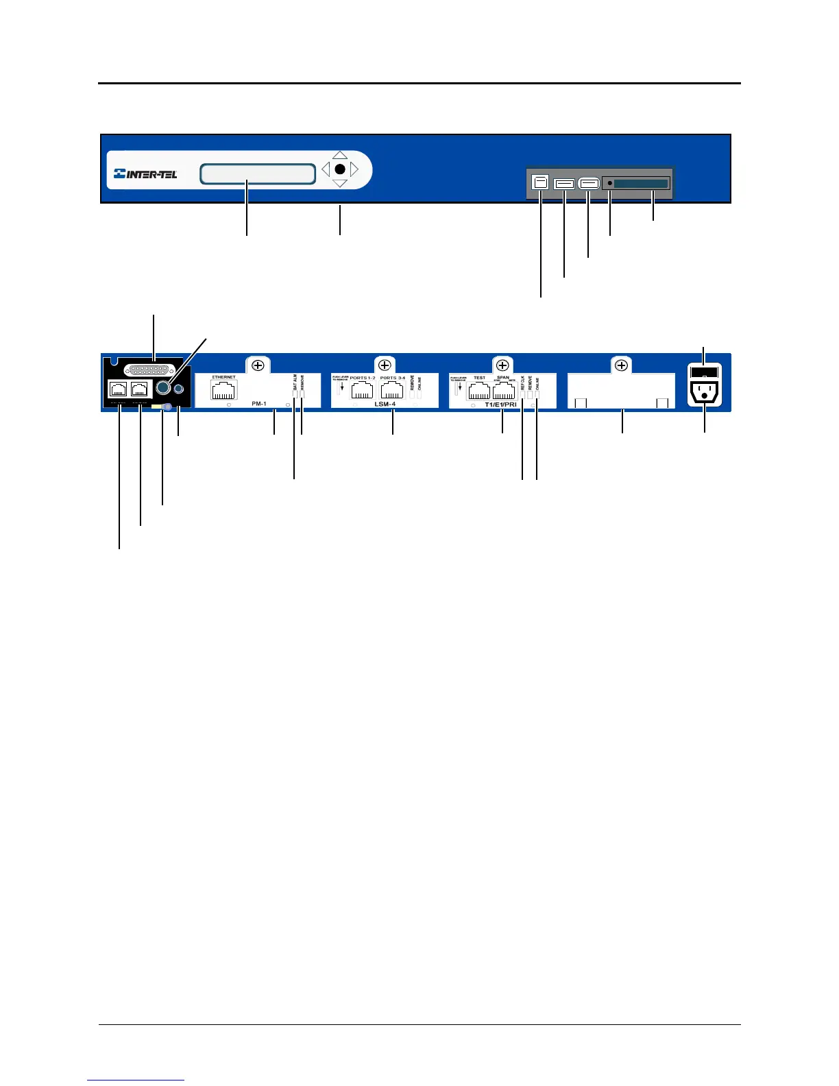
CompactFlash
®
Card
KEY (security) recessed
USB-A (USB hub; UPS cable; or,
USB-B
PowerQuad LSProcessorMusic On
Hold Port
Paging Port
Optional External Voice Mail or DEI
or Digital Expansion Interface (DEI)
(2) Single Line Ports
(2) Loop Start Ports
Base Server Back
Base Server Front
2-Line LCD Panel
Ground Lug (Earth ground)
T1/E1/PRI
LCD Panel Controls
ModuleModuleModule
Fuse
* The Base Server is shipped without modules installed. The above examples are for
illustrative purposes only. Module covers must remain in place if there is not an actual module
to occupy a module bay. The covers help to ensure foreign material does not enter the chassis.
Module
Cover*
Eject Button
Remove
Battery Alarm LED
Module LED
Online
Status
LED
REF
Clock
LED
EXP
DUAL LS
DUAL SL
PAGE MOH
Basic Voice Mail backup)
 Loading...


