Chapter 5: Installation
Running Cables to Endpoints
Inter-Tel
®
5000 Installation Manual – Issue 2.4, May 2008 Page 5-55
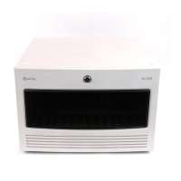
• Install the Inter-Tel DEI chassis near the MDF in an Inter-Tel or other rack. Also, mount the
chassis in the rack at a height appropriate for reading the Status panel. Allow room above
and below the chassis for later expansion. If wall-mounting is desired, contact the Inter-Tel
CommSource Division for information.
See page 5-15 and Figure 5-1 on page 5-15, Figure 5-32 on page 5-64, Figure 5-33 on
page 5-65, and Figure 5-39 on page 5-74 for examples.
• Install a patch panel in the rack above the location you will install the Inter-Tel 5000 Base
Server.
A patch panel allows for convenient cable terminations from the MDF, and a patch panel
allows you to use patch cables (for T1M or T1M-2 modules) or modular line cord cables
(built-in dual Loop Start and LSM-2/-4 modules). Run cabling from the MDF 66-block to
the patch panel in the rack.
• Install the DEM-16(s) in the chassis—see page 5-74.
• Install the optional LSM-4 module in the chassis—see page 5-42.
• Install the optional BRM-S module in the chassis—see page 5-48.
• Install an uninterruptible power supply (UPS). For more information, see “Uninterruptible
Power Supply (UPS) Connections” on page 4-6. Plug only the Inter-Tel DEI chassis into
this UPS.
• Connect the modules to MDF blocks or to a patch panel using appropriate cabling—see
page 5-33. If replacing an Inter-Tel Axxess
®
system, a 15 ft (4.5720 m) Amphenol-to-DEM-
16 cable is available, part no. 813.1814.
• Ground the chassis—see page 5-16.
• Power up the system—see page 5-87.
• If this is an upgrade, do the following:
o Perform a database backup.
o Start an Administrative Web Session and upgrade the system software.
• Install the current DB Programming version. Upload the current license file, as applicable
to your site. Disable Basic Voice Mail before attaching an external voice processing
system. To disable BVM, from the DB Programming menu bar, select Operations – Voice
Processing Operations – Disable Basic Voice Mail.
• Install the optional external voice processing system, if applicable. See page 5-172.
• Install any optional system equipment, external paging network, external music source,
headsets, handset amplifiers, etc. Install an uninterruptible power supply (UPS) with all
units. See “Uninterruptible Power Supply (UPS) Connections” on page 4-6.
• Ensure that all equipment is working properly.
• For additional information, refer to the Inter-Tel 5000 Features and Programming Guide
(part no: 580.8006).
Running Cables to Endpoints
Carry out the following guidelines when running cable for digital endpoints:
• Develop floor plans to aid in proper digital endpoint cabling in a star (home run)
configuration from the Inter-Tel DEI chassis. If necessary, run the necessary cabling to
where the digital endpoint will be used. See “Cabling to Endpoints” on page 4-10.
• If desired, two- or three-pair twisted cable and four- or six-conductor modular jacks [line
jack units] may be used for all endpoint connections. This allows the various endpoint
types to be easily interchanged, if necessary. (If three-pair cable is used with a U.S.
system, extra terminal blocks and the use of cross-connect wiring techniques are
required.)
• Install proper type cable for the application according to the National Electrical Code and
local building codes [BS 6701 in Europe].


 To Next Page