– Dash Panel
WIRING HARNESS
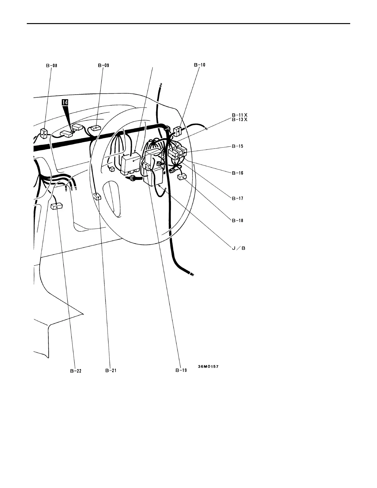
CONFIGURATION DIAGRAMS
Interior relay box
B-7
B-19 (22) Body harness and instrument panel harness
combination
B-21 (2) Stop lamp switch (driver side)
B-22 (16-B) Diagnosis connector
B-24 (26-Y) ABS-ECU
B-25 (16) ABS-ECU
B-26 (2-B) Diode (for ABS circuit)
B-27 (4) Engine control relay
B-28 (4) Fuel pump relay
B-29 (4-B) A/T relay
B-30 (14) Radio or spare connector for radio
B-31 (1) Glass antenna amplifier
B-32 (19-B) Jumper connector (5)
B-33 (2) Blower motor
<vehicles with fully automatic air conditioner>
B-34 (4) Blower high speed relay <vehicles with fully
automatic air conditioner>
B-35 (22) Body harness and front door harness (LH)
combination
B-36 (2) Inside and outside air change-over damper
motor <vehicles with fully automatic air
conditioner>
B-37 (4) Power transistor <vehicles with fully automatic
air conditioner> or resistor <vehicles with
heater or manual air conditioner>