REAR AXLE – Drive Shaft
27-36
DRIVE SHAFT
REMOVAL AND INSTALLATION
Pre-removal Operation
(1) Gear Oil Draining (Refer to P.27-28.)
(2) Center Exhaust Pipe Removal
(Refer to GROUP 15.)
Post-installation Operation
(1) Checking Each Ball Joint Dust Cover for Cracks
and Damages by Pressing Dust Cover with Finger
(2) Center Exhaust Pipe Installation
(Refer to GROUP 15.)
(3) Gear Oil Filling (Refer to P.27-28.)
(4) Parking Brake Lever Stroke Check and Adjustment
(Refer to GROUP 36 – On-vehicle Service.)
(5) Wheel Alignment Check and Adjustment
(Refer to GROUP 34 – On-vehicle Service.)
1
2
3
4
5
6
7
8
9
10
11
Unit: Nm {kgf@m}
25 {2.6}
74 – 87 {7.5 – 8.9}
74 – 87
{7.5 – 8.9}*
88 {9.0}*
49 – 59 {5.0 – 6.0}
196 – 255 {20.0 – 26.0}
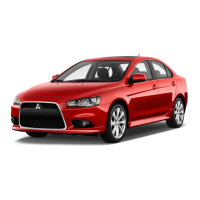
Removal steps
1. Caliper assembly
(Refer to P.27-33.)
2. Brake disc
3. Shoe & lining assembly (Refer to
GROUP 36 – Parking Brake.)
4. Clip
5. Parking brake cable connection
AA""BA 6. Drive shaft nut
7. Rear speed sensor coupling
<vehicles with AYC>
8. Trailing arm coupling
9. Lower arm coupling
10. Toe control arm coupling
AB""AA 11. Drive shaft
Caution
(1) With the part marked with *, first temporarily
tighten it, then ground the vehicle and tighten
it to specification in unloaded condition.
(2) When removing the drive shaft from, and
reinstalling it to, a vehicle with AYC, use care
not to damage the rotor mounted on the BJ outer
race.
 Loading...