REAR AXLE – Knuckle
27-35
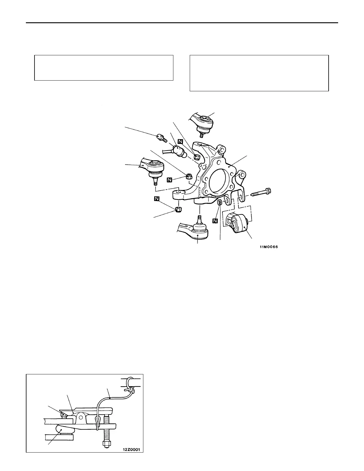
KNUCKLE
REMOVAL AND INSTALLATION
Pre-removal Operation
D Rear Hub Assembly and Backing Plate Removal
(Refer to P.27-33.)
Post-installation Operation
(1) Check Each Ball Joint Dust Cover for Cracks or
Damage by Pushing It with Finger.
(2) Rear Hub Assembly and Backing Plate Installation
(Refer to P.27-33.)
1
2
3
4
5
6
Unit: Nm {kgf@m}
25 {2.6}
74 – 87
{7.5 – 8.9}
74 – 87
{7.5 – 8.9}*
74 – 87
{7.5 – 8.9}
88 {9.0}*
Removal steps
1. Rear speed sensor connection
<Vehicles with AYC>
AA" 2. Trailing arm connection
3. Lower arm connection
AA" 4. Toe control arm connection
AA" 5. Upper arm connection
6. Knuckle
Caution
*: Indicates parts which should be temporarily
tightened, and then fully tightened with the
vehicle on the ground in the unladen condition.
REMOVAL SERVICE POINT
AA" TRAILING ARM / TOE CONTROL ARM / UPPER
ARM DISCONNECTION
Caution
(1) Use the special tool to loosen the nut only; do not
remove it from the ball joint.
(2) Tie the special tool with a cord not to let it fall off.
MB990635,
MB991113 or
MB991406
Nut
Cord
Ball joint