REAR SUSPENSION – Rear Suspension Assembly
34-4
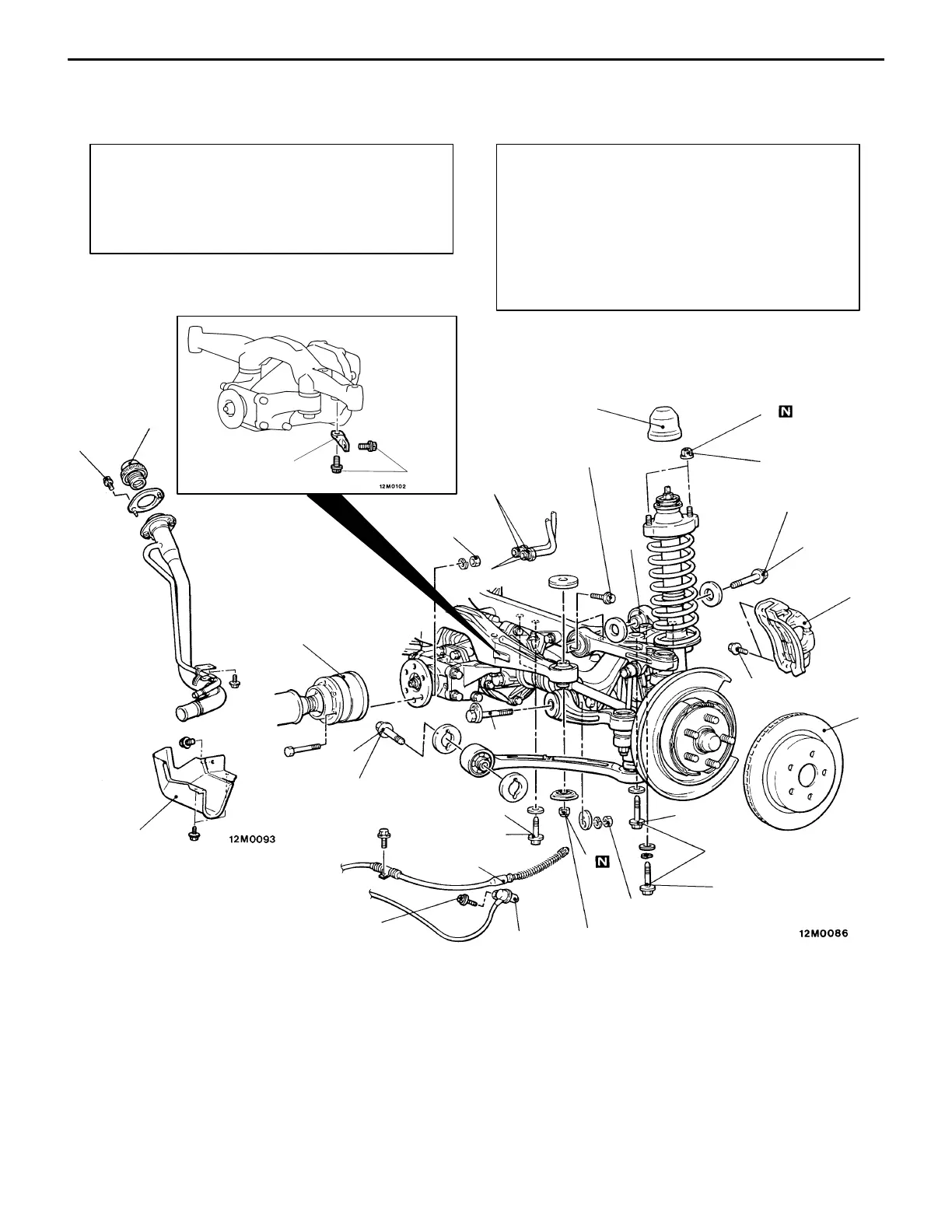
REAR SUSPENSION ASSEMBLY
REMOVAL AND INSTALLATION
Pre-removal Operation
(1) Center Exhaust Pipe Removal
(Refer to GROUP 15.)
(2) Trunk Room Side Trim Removal <GSR>
(3) AYC Fluid Draining
(Refer to GROUP 27 – On-vehicle Service.)
Post-installation Operation
(1) AYC Fluid Refilling and Bleeding
(Refer to GROUP 27 – On-vehicle Service.)
(2) Center Exhaust Pipe Installation
(Refer to GROUP 15.)
(3) AYC Operation Check
(4) Parking Brake Cable Stroke Check
(Refer to GROUP 36 – On-vehicle Service.)
(5) Wheel Alignment Check and Adjustment
(Refer to P.34-3.)
1
3
4
5
6
7
9
10
11
12
13
14
15
16
17
Unit: Nm {kgf@m}
44 {4.5}
108 – 127 {11.0 – 13.0}
54 {5.5}
88 {9.0}
93 {9.5}*
88 {9.0}
15
8
2
15
29 – 34
{3.0 – 3.5}
25 {2.6}
34 {3.5}
25 {2.5}
69
{7.0}
Toe control bar
EVOLUTION-V RS
137 – 156 {14.0 – 16.0}*
59 – 68 {6.0 – 7.0}*
Removal steps
1. Fuel filler cap
2. Bolt
3. Filler neck protector
4. Cap
5. Shock absorber mounting nut
AA" 6. Brake caliper assembly
7. Rear speed sensor <vehicles with
AYC>
8. Brake disc
9. Parking brake cable end (Refer to
GROUP 36.)
10. AYC fluid line connection <vehicles
with AYC>
AB""BA 11. Propeller shaft connection
12. Upper arm mounting bolt
13. Trailing arm mounting bolt
14. Toe control arm mounting bolt
AC""AA 15. Crossmember mounting bolt
16. Differential support assembly
mounting bolt
17. Rear suspension assembly
Caution
The parts marked with * should be first temporarily
tightened, then torqued to specification with the
vehicle on the ground in unloaded condition.