– Engine Compartment
WIRING HARNESS
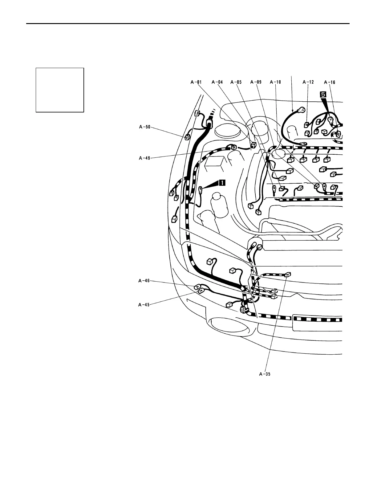
CONFIGURATION DIAGRAMS
Connector
symbol
–01
thru
–50
A
Ground cable
B-2
WIRING HARNESS CONFIGURATION DIAGRAMS
ENGINE COMPARTMENT
A-01 (2-B) Brake fluid level switch
A-03 (1-B) Noise condenser
A-04 (1) Alternator
A-05 (4-GR) Alternator
A-09 (1-B) Starter
A-10 (1) Starter
A-12 (2-B) Fuel pressure solenoid valve
A-16 (4-B) Throttle position sensor
A-18 (6-B) Idle speed control servo
A-19 (3-B) Vehicle speed sensor
A-20 (4-B) Windshield wiper motor
A-21 (8-B) Hydraulic unit <vehicles with ABS>
A-22 (2-B) Hydraulic unit <vehicles with ABS>
A-23 (2-B) Waste gate solenoid valve
A-25 (7-B) Air flow sensor
A-26 (2-B) Front speed sensor (LH)
<vehicles with ABS>
A-28 (8-B) Control harness and front harness
combination