REAR SUSPENSION – Upper Arm Assembly
34-6
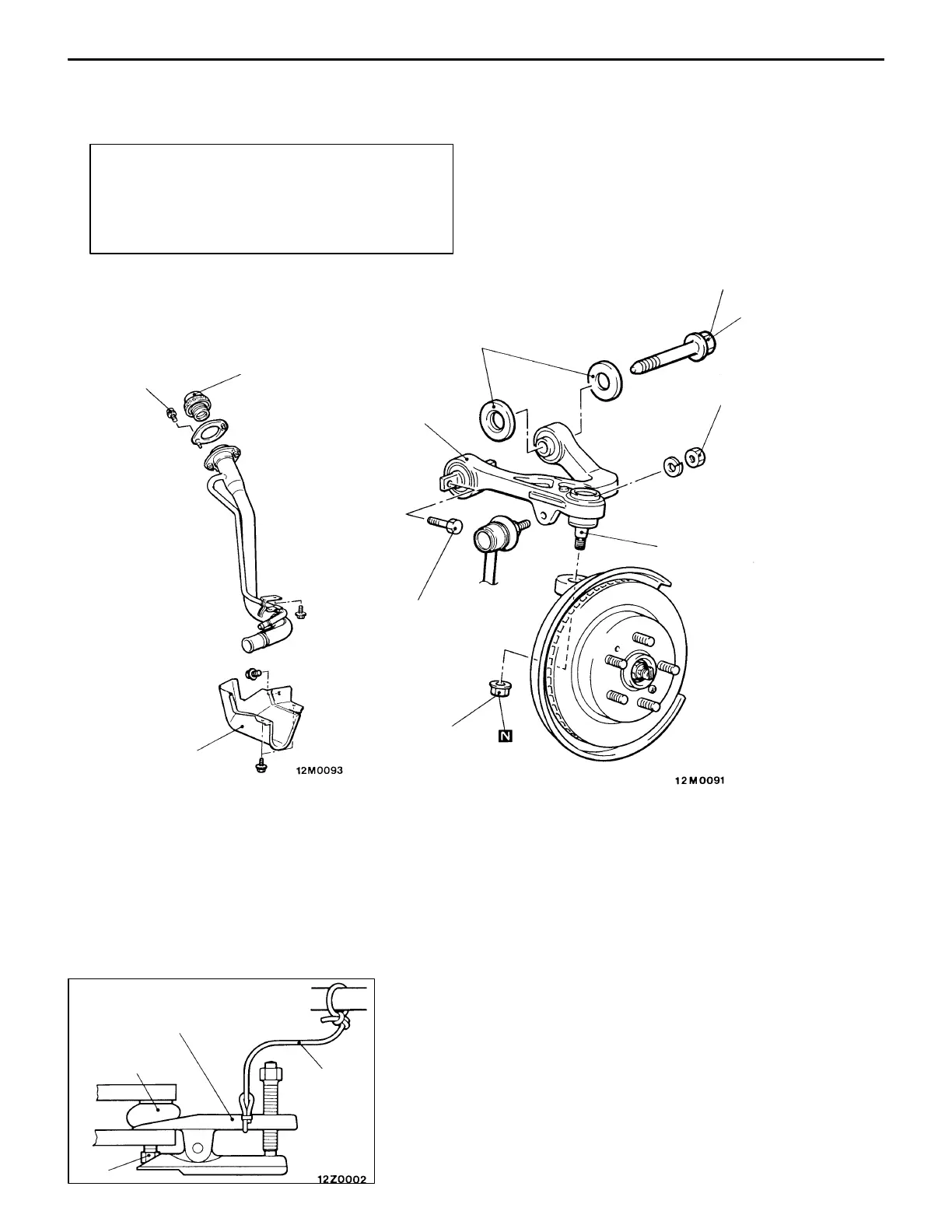
UPPER ARM ASSEMBLY
REMOVAL AND INSTALLATION
Post-installation Operation
(1) Push the Dust Cover of the Upper Arm Ball Joint
with a Finger to Check for Possible Cracks or
Damage.
(2) Wheel Alignment Check and Adjustment
(Refer to P.34-3.)
1
2
3
4
5
6
7
Unit: Nm {kgf@m}
49 {5.0}
59 – 69 {6.0 – 7.0}*
74 – 87 {7.5 – 8.9}
39 {4.0}
Removal steps
1. Fuel filler cap
K
2. Bolt
K
3. Filler neck protector
K
AA" 4. Upper arm assembly to knuckle
coupling
5. Upper arm assembly mounting bolt
6. Stopper
7. Upper arm assembly
NOTE
Parts marked with
K
apply only when RH side is removed
and installed.
Caution
The part marked with * should be first temporarily
tightened, then torqued to specification with the
vehicle on the ground in unloaded condition.
REMOVAL SERVICE POINT
AA" UPPER ARM ASSEMBLY DISCONNECTION
FROM KNUCKLE
Caution
(1) Only loosen the nut, and not remove it from the ball
joint, and use the special tool.
(2) Hang the special tool with a string to prevent the
parts including the tool from falling apart.
MB990635,
MB991113 or
MB991406
Nut
String
Ball joint