MPI – Troubleshooting
13-8
2. INSPECTION CHART FOR DIAGNOSIS CODES
Code No. Diagnosis item Reference page
12 Air flow sensor (AFS) system 13-8
13 Intake air temperature sensor system 13-9
14 Throttle position sensor (TPS) system 13-9
21 Engine coolant temperature sensor system 13-10
22 Crank angle sensor system 13-11
23 Camshaft position sensor system 13-11
24 Vehicle speed sensor system 13-12
25 Barometric pressure sensor system 13-13
31 Detonation sensor system 13-14
41 Injector system 13-14
44 Ignition coil and power transistor unit system 13-15
64 Alternator FR terminal system 13-16
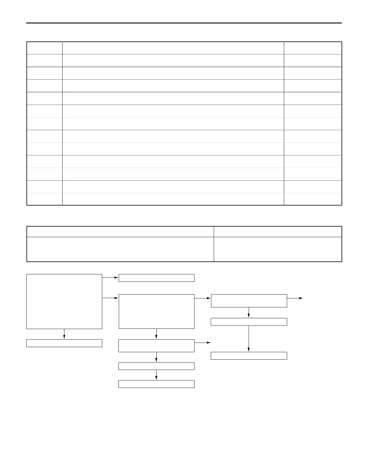
3. INSPECTION PROCEDURE FOR DIAGNOSIS CODES
Code No. 12 Air flow sensor (AFS) system Probable cause
Range of Check
D Engine speed is 500 r/min or more.
Set conditions
D Sensor output frequency is 3 Hz or less for 4 seconds.
D Malfunction of the air flow sensor
D Improper connector contact, open circuit or
short-circuited harness wire of the air flow sensor
D Malfunction of the engine-ECU
Measure at the air flow sensor con-
nector A-25.
D Connect the connector. (Use
the test harness: MB991709)
1. Voltage between 3 and earth
(Engine: Idling)
OK: 2.2–3.2 V
2. Voltage between 7 and earth
OK: 0–1 V (Engine: idling)
6–9 V (2,000 r/min)
OK
Replace the engine-ECU.
1. NG
Check the air flow sensor circuit.
2. NG
Measure at the engine-ECU con-
nector B-59.
D Connect the connector.
D Voltage between 19 and earth
(Ignition switch: ON)
OK: 6–9 V
OK
Check the following connector:
B-59
OK
Check trouble symptom.
NG
Replace the engine-ECU.
NG
Check the following connector:
A-25
NG
Repair
OK
Check trouble symptom.
NG
NG
Repair
Replace the air flow sensor.
 Loading...