MPI – Troubleshooting
13-14
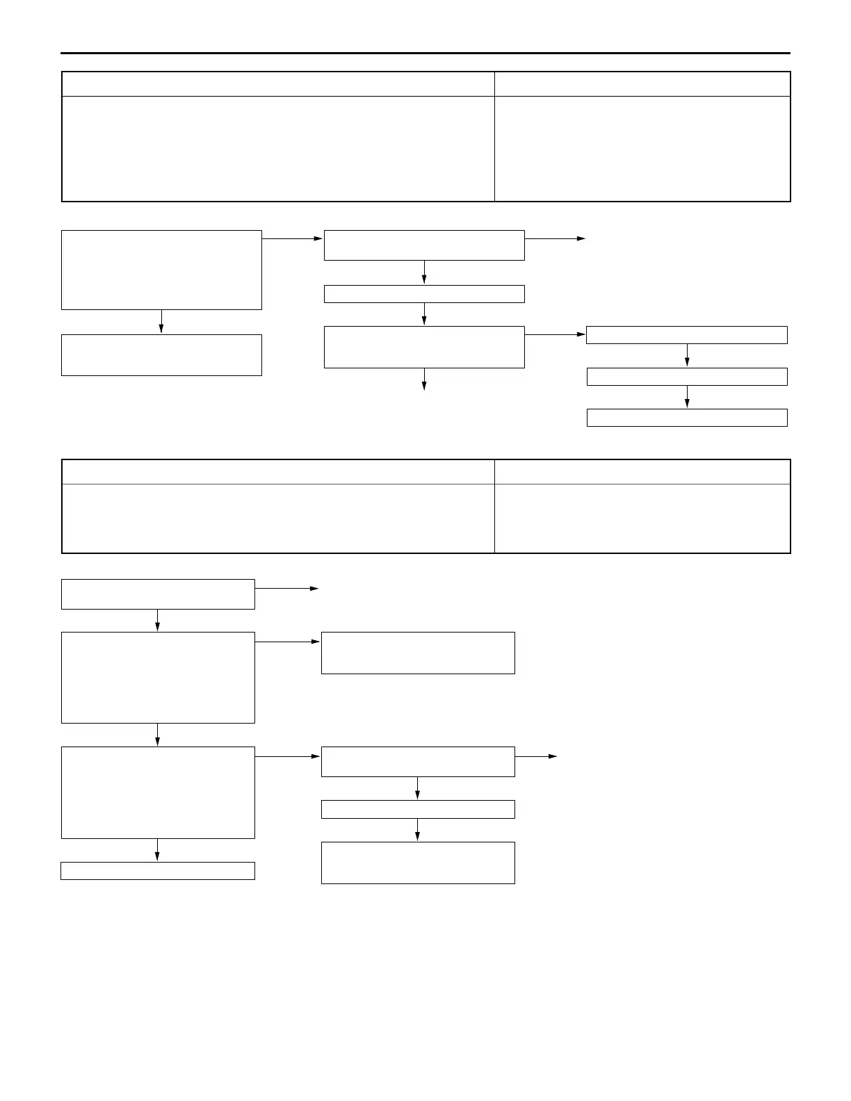
Code No.31 Detonation sensor system Probable cause
Range of Check
D Ignition switch: ON
D Excluding 60 seconds after the ignition switch is turned to ON or immediately
after the engine starts.
D Engine speed is approx. 5,000 r/min or more
Set conditions
The change in the detonation sensor output voltage (detonation sensor peak voltage
at each 1/2 revolution of the crankshaft) is less than 0.06 V for 200 times in succession.
D Malfunction of the detonation sensor
D Improper connector contact, open circuit or
short-circuited harness wire of the detonation sensor
circuit
D Malfunction of the engine-ECU
Measure at the detonation sensor con-
nector A-96.
D Disconnect the connector and
measure at the harness side.
D Continuity between 2 and earth
OK: Continuity
OK
Check the following connector:
B-62
NG
Repair
OK
Check trouble symptom.
NG
Check the harness wire between the
engine-ECU and the detonation sensor
connector.
OK
Replace the detonation sensor.
Check trouble symptom.
NG
Replace the engine-ECU.
NG
Repair
NG
Check the harness wire between the
detonation sensor and earth, and repair
if necessary.
Code No. 41 Injector system Probable cause
Range of Check
D Engine speed is approx. 50–1,000 r/min
D The throttle position sensor output voltage is 1.15 V or less.
Set conditions
D Surge voltage of injector coil is not detected for 4 seconds.
D Malfunction of the injector
D Improper connector contact, open circuit or
short-circuited harness wire of the injector circuit
D Malfunction of the engine-ECU
NG
Check the harness wire between the
resistor and the injector connector, and
repair if necessary.
OK
Check trouble symptom.
OK
Check the injector control circuit.
OK
Measure at the injector connectors
A-53, A-54, A-55, A-56.
D Disconnect the connector, and
measure at the harness side.
D Voltage between 1 and earth
(Ignition switch: ON)
OK: System voltage
NG
Check the following connector:
A-125
NG
Repair
Check the injector. (Refer to P.13-34.)
Check the resistor. (Refer to P.13-34.)
NG
Replace
OK
Measure at the resistor connector
A-125.
D Disconnect the connector, and
measure at the harness side.
D Voltage between 3 and earth
(Ignition switch: ON)
OK: System voltage
NG
Check the harness wire between the
control relay and the resistor connec-
tor, and repair if necessary.
 Loading...