FRONT AXLE – Axle Hub and Knuckle
26-3
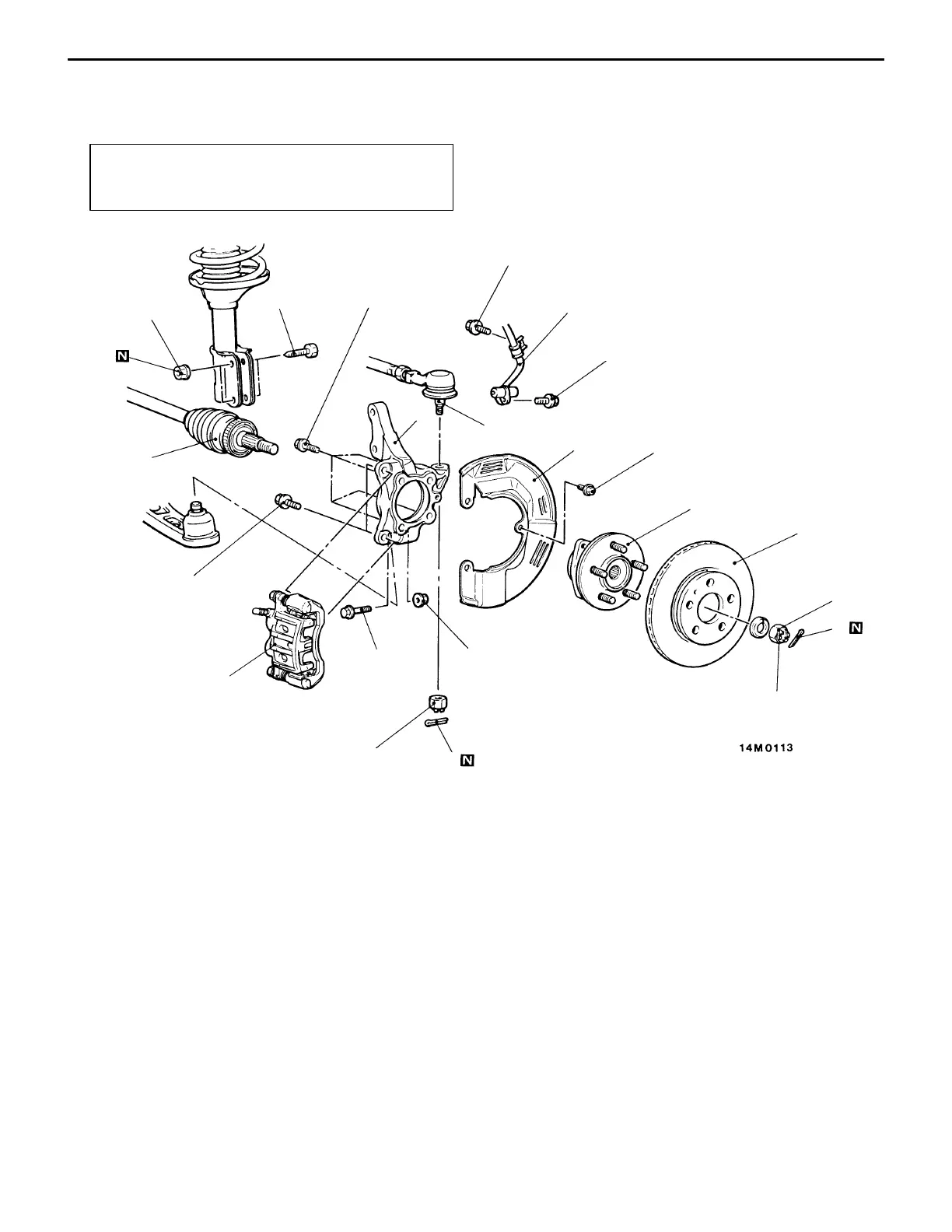
AXLE HUB AND KNUCKLE
REMOVAL AND INSTALLATION
Post-installation Operation
D Check the Dust Cover for Cracks or Damage by
Pushing it with Finger.
1
2
3
4
5
6
7
8
9
10
11
12
13
Unit: Nm {kgf@m}
88 {9.0}
108 – 127
{11.0 – 13.0}
90 – 110
{9.2 – 11.2}
15 – 33
{1.5 – 3.4}
177 – 275
{18.0 – 28.0}
25 {2.6}
25 {2.6}
9 {0.9}
113 {11.5}
Removal steps
1. Front speed sensor
<Vehicles with AYC>
AA" 2. Caliper assembly
3. Brake disc
4. Split pin
AB""AA 5. Drive shaft nut
6. Front hub assembly
7. Dust shield
8. Connection for lower arm ball joint
9. Split pin
AC" 10. Connection for tie rod end
AD" 11. Front drive shaft
12. Front strut mounting bolt
13. Knuckle
Caution
(1) For vehicles with AYC, be careful when handling
the pole piece at the tip of the speed sensor
so as not to damage it by striking against other
parts.
(2) For vehicles with AYC, be careful not to damage
the rotors installed to B.J. outer race during
removal and installation of the drive shaft.
 Loading...