REAR AXLE – Troubleshooting <AYC>
27-26
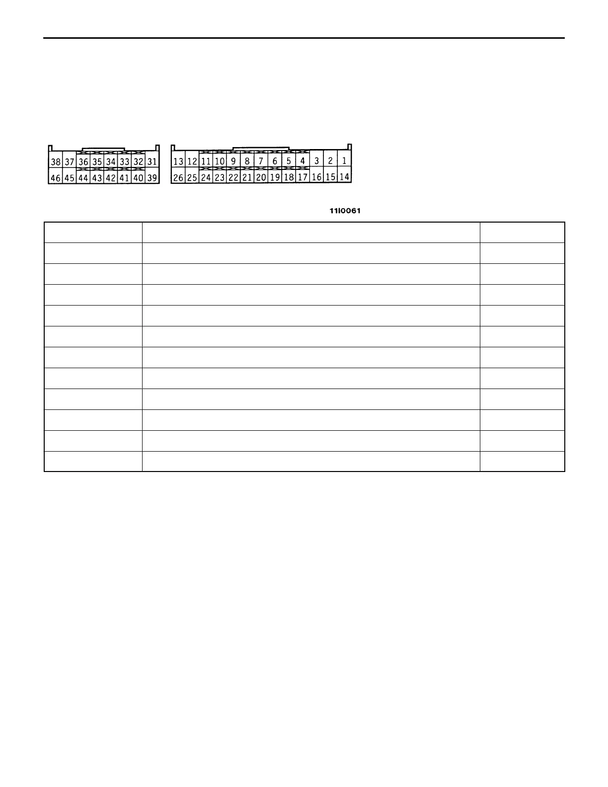
7-2 LISTING OF RESISTANCE AND CONTINUITY ACROSS CONNECTOR TERMINALS ON
HARNESS SIDE
(1) Measure the resistance and check for continuity with the ignition switch in the “OFF” position and
AYC-ECU connector disconnected.
(2) Measure the resistance and check for continuity across terminals listed below.
(3) Fig. below shows the arrangement of terminals.
Terminal No. Signal name Normally
2 – body ground Longitudinal acceleration sensor ground, lateral acceleration sensor ground Conducting
26 – body ground ECU ground Conducting
35 – body ground AYC motor relay Conducting
37 – body ground Directional control valve (right) 15.4 – 16.4 Ω
38 – body ground Proportioning valve 3.4 – 4.0 Ω
45 – body ground Directional control valve (left) 15.4 – 16.4 Ω
46 – body ground ECU ground Conducting
6 – 19*
2
Speed sensor (front, RH) 1.4 – 1.8 Ω
7 – 20*
2
Speed sensor (front, LH) 1.4 – 1.8 Ω
8 – 21*
2
Speed sensor (rear, RH) 1.4 – 1.8 Ω
9 – 22*
2
Speed sensor (rear, LH) 1.4 – 1.8 Ω
NOTE
*2: Indicates the vehicles without ABS.
 Loading...