POWER PLANT MOUNT – Roll Stopper and Centermember
32-2
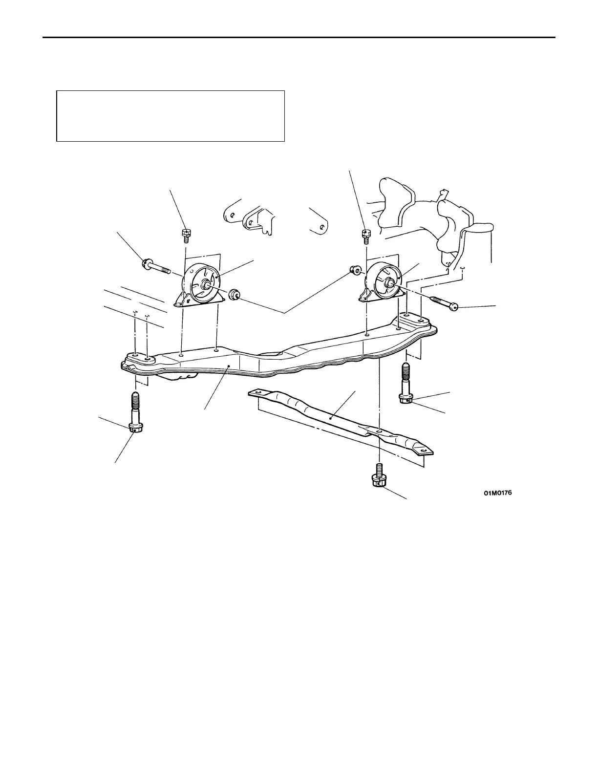
ROLL STOPPER AND CENTERMEMBER
REMOVAL AND INSTALLATION
Caution
When tightening the portion marked with *, first
temporarily tighten it, then torque to specification
with the engine weight applied to the body.
1
2
34
5
Unit: Nm {kgf@m}
52 {5.3}*
2
2
34 {3.5}
34 {3.5}
93 {9.5}
69 {7.0}
93 {9.5}
2
Removal steps
1. Front crossmember bar <vehicles
with 17’ wheels>
2. Bolt
"BA 3. Front roll stopper bracket assembly
"AA 4. Rear roll stopper bracket assembly
5. Centermember
NOTE
The conventional service procedures apply for the
installation service points.
 Loading...