– Engine Compartment
WIRING HARNESS
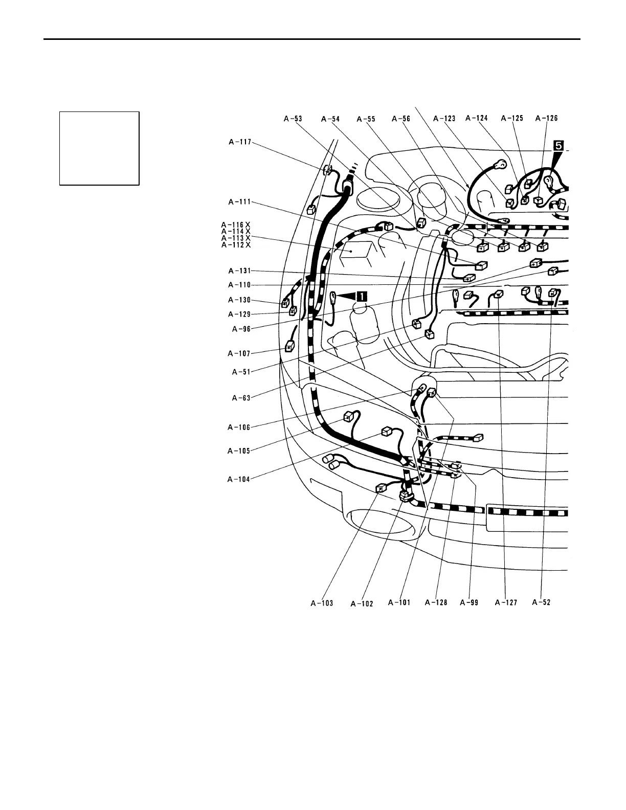
CONFIGURATION DIAGRAMS
Connector
symbol
–51
thru
–131
A
Ground cable
B-4
A-51 (3-B) Crank angle sensor
A-52 (1-B) Oil pressure switch
A-53 (2-B) Injector (No.1)
A-54 (2-B) Injector (No.2)
A-55 (2-B) Injector (No.3)
A-56 (2-B) Injector (No.4)
A-63 (2-B) O
2
sensor
A-72 (2-B) Back-up lamp switch
A-73 (1-L) Engine speed detection connector
A-74 (1-B) Fuel pump check connector
A-76 (6) Valve relay <vehicles with ABS>
A-77 (5) Motor relay <vehicles with ABS>
A-78 (2-GR) Side turn signal lamp (LH)
A-80X (5) Horn relay <vehicles with SRS air bag>
A-82X (5) Radiator fan relay (LO)
A-84X (5) Headlamp relay
A-86X (4) Alternator relay
A-88 (6-B) Control harness and battery harness
combination
A-89 (2-BR) Front turn signal lamp (LH)
A-90 (3-B) Headlamp (LH)
A-91 (2) Position lamp (LH)
A-92 (2-B) Fog lamp (LH)
A-94 (4-GR) Radiator fan motor
A-96 (2-GR) Knock sensor